Physics: Studying the application of Ohm's law for DC circuits, Laboratory work. Laboratory work. Learning Ohm's Law for a Circuit Section
Ohm's and Kirchhoff's laws
Lab #1
in the discipline "Electrical Engineering and Electronics"
Objective:
1. General guidelines
The experimental part of the laboratory work is carried out virtually using the Electronics Workbench program, which simulates a real electronic laboratory equipped with real-time measuring instruments. Version 4.1 of this program is in the IOS "Avanta" (see the menu item "Materials", Tools).
Before performing laboratory work, the student must familiarize himself with the Electronics Workbench program and study the materials of lesson No. 1 "BASIC CONCEPTS OF THE THEORY OF ELECTRIC CIRCUITS. OHM AND KIRCHHOFF LAWS AND THEIR USE FOR CALCULATIONS OF ELECTRIC CIRCUITS."
Laboratory work is carried out in accordance with its option.
The laboratory work report should contain: a title page, a statement of the purpose of the work, circuits of the circuits under study, tables with the results of measurements and calculations, conclusions about the work done. Text pages should correspond to A4 format, Times New Roman font - 12 pt, alignment - in width, red line (indent) - 1.25 cm, line spacing - 1.5, automatic word wrap.
2. An example of the performance of work and the design of the report
2.1.Title page of the lab report
Ministry of Education and Science of the Russian Federation
Vladivostok State University
economy and service
Department of Electronics
on laboratory work No. 1
in the discipline "Electrical Engineering and Electronics"
Ohm's and Kirchhoff's laws
gr. _____________ _____________________ ()
Teacher
assistant professor _____________________
Vladivostok 200__
2.2. Completing of the work
Objective: experimental verification of the operation of Ohm's and Kirchhoff's laws, study of the relationship between the parameters of measuring instruments and measurement accuracy.
1. In the Electronics Workbench program, we select the necessary radio elements and assemble the circuit, the diagram of which is given in the task (Scheme 1).
EMF source E = 50 V;
source resistance Ri = 2 kOhm;
load resistance Rn = 20 kOhm.
1.1. Let's connect the measuring devices in accordance with scheme 2. Set the parameters of the measuring devices:
resistance of voltmeters V1 and V2 RV = 250 kOhm;
ammeter resistance A RA \u003d 0.3 Ohm.
On the screen we get the following picture:
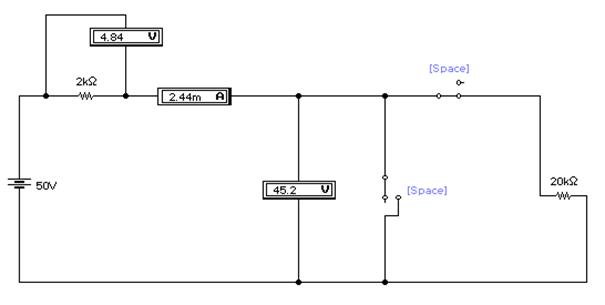
Rice. 1.1. Diagram of a circuit assembled in Electronics Workbench
1.2. Let's check the fulfillment of Ohm's law for the complete circuit (the key SA2 is closed, the key SA1 is open). To do this, you need to measure the voltage Ui across the resistor Ri with a voltmeter V1, the voltage Un across the resistor Rn with a voltmeter V2, and the current I with an ammeter A. We obtained the measurement results after turning on the circuit, as shown in fig. 1.1: I=2.44mA; Ui = 4.84V; Un=45.2V.
Calculate the voltage across the resistor Ri, the voltage across the resistor Rn and the current in the circuit using the Ohm formula. To do this, you need to find the equivalent resistance of the circuit:
Reqv = Rand + Rn = 2 + 20 = 22 kOhm.
The current in the circuit I will be equal to:
I \u003d E / Req \u003d 50/22 "2.27 mA.
where Imeas is the measured current value;
Icalc - calculated current value.
Ui \u003d IRi \u003d 2.27 mA × 2 kOhm \u003d 4.54 V.
Load voltage Un:
Un = IRn = 2.27 mA × 20 kOhm = 45.46 V.
Let's find the relative errors of voltage measurement dUi and dUn:
where U and meas; Un meas - measured voltages on the source resistance and load;
Ui calculated; Un calc - voltages on the source resistance and load calculated.
We will enter all the measured and calculated currents and voltages in Table. one.
1.3. In the circuit under study, open the key SA2, thereby realizing the idle mode. Let's take readings of measuring instruments (Fig. 1.2): I = 198 μA; Ui=394mV; Un=49.6V.
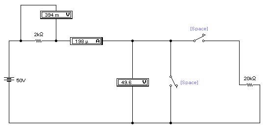
Rice. 1.2. Idle mode
Let's check the measurements with theoretical calculations.
Under ideal conditions, the current in the circuit in idle mode is zero: I=0. It follows from this that the voltage across the source resistance will also be zero: Ui=IRi=0. The voltage on the load will be equal to the voltage of the EMF source: Un=E=50V.
We see that the readings of the voltmeters V1 and V2 and the ammeter A differ from these data. This is due to the imperfection of measuring instruments, which have their own resistance.
Let's calculate the relative error of voltage measurement on the load:
We will enter all the data obtained in the table. one.
1.4. Now we implement the short circuit mode. To do this, close the key SA1. Let's take readings of measuring instruments (see Fig. 1.3): I = 49.6 mA; Ui=49.5mV; Un=0V.
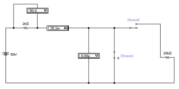
Rice. 1.3. Short circuit mode
Let's check the measurements with theoretical calculations. Calculate the voltage across the resistor R and the current in the circuit.
The current I in the circuit will be equal to:
I \u003d E / R and \u003d 50/2 "25 mA.
Let's compare the measured and calculated current values. To do this, we find the relative error of current measurement dI:
Voltage across the source resistance Ui:
Ui = IRi = 25 mA × 2 kΩ = 50 V.
This matches the voltmeter reading. Relative voltage measurement error dUi=0.
The voltage at the load is zero, since the load resistance Rн=0.
We will enter all the results of calculations and measurements in Table. one.
Table 1
Results of measurements and calculations of voltages and currents in the circuit
Ui meas, kOhm | Un meas, kOhm | Un calc, kOhm | |||||||
Ohm's law for a complete circuit | |||||||||
Idle mode | |||||||||
Short circuit mode |
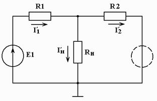
2. In the Electronics Workbench program, we select the necessary radio elements and assemble a resistive circuit, the diagram of which is given in the task (Scheme 2).
Set the parameters of the circuit elements:
EMF of the first source E1 = 12 V;
EMF of the second source E2 = 15 V;
resistance R1 = 1 kOhm;
resistance R2 = 2 kOhm;
load resistance Rn = 3 kOhm.
2.1. Connect the measuring devices in accordance with the scheme of the resistive circuit 2. Set the parameters of the measuring devices:
resistance of voltmeters V1, V2 and V3 RV = 350 kOhm;
resistance of ammeters A1, A2 and A3 RA \u003d 0.2 Ohm.
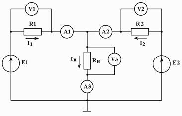
On fig. 2.1 shows the circuit that we have collected.
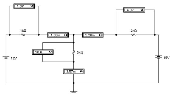
Rice. 2.1. Diagram of a circuit assembled in Electronics Workbench
On virtual measuring instruments, we see the following readings (Fig. 2.1): I1=1.38mA, I2=2.20mA, In=3.57mA; U1 \u003d 1.37V, U2 \u003d 4.37V, Un \u003d 10.6V. Let's write them down in the table. 2.
2.2. We calculate all currents and voltages in the circuit using the formulas of Ohm's and Kirchhoff's laws.
First, we determine the currents in the branches. Using the superposition method, we exclude the source of emf E2 from the circuit:
Find the equivalent circuit resistance:
Currents in two parallel branches:
![]()
Now we exclude the source of EMF E1:
![]()
Let's calculate the currents:
Using the superposition method, we calculate the currents in the branches of the circuit:
Let's define stresses:
Let's add the calculated results of currents and voltages to the table. 2.
To compare the measured and calculated results, we determine the relative measurement errors:
![]()
![]()
![]()
![]()
![]()
table 2
The values of currents and voltages in the circuit under study
measured values | ||||||
Calculated values | ||||||
Relative measurement error |
2.3. By changing the value of the EMF E1, we will try to ensure that the current through the resistor R1 becomes zero. This happened when (see Fig. 2.4)
E1 \u003d 8.98979 V » 8.99 V.
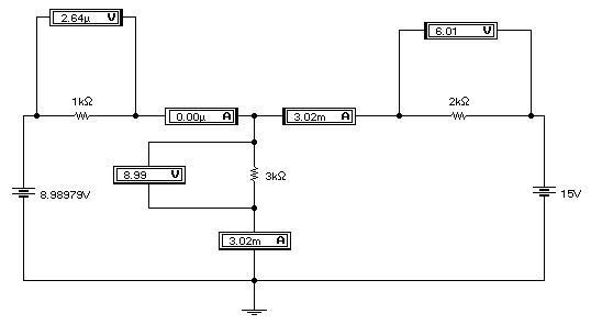
Rice. 2.2. Circuit diagram, in which the current through the resistor R1 became zero
Conclusion
As a result of the work done, the following conclusions can be drawn:
1. Comparing the measured values of currents and voltages in the circuit with those calculated according to Ohm's and Kirchhoff's laws, we were convinced that they really work.
2. The values of the measured currents and voltages in the circuit differ from those calculated due to the imperfection of the measuring instruments, which have their own resistance.
3. In our case, in scheme 2, both sources give energy to the load.
4. When two sources are connected to the circuit, one of them may not give up its energy, but take it from the other, depending on the voltage value at this source. For example, in our case, this voltage was 8.99 V.
.
Let the tension vector be directed along the axis Oh, then the acceleration of the particle is also directed along this axis and is equal to . If the initial velocity of the particle is zero, then at the moment of time t it is equal to average speed half as much, for some time interval τ it is equal to
Let's take this model. We assume that moving charged particles collide with other particles after the same time τ, which can be identified with the average time between collisions. We will assume that, on average, as a result of the collision, the particles stop, and after that they again begin to move in the electric field with a zero initial velocity. For this reason, we can assume that particles move in an electric field with an average speed given by formula (1).
|
|
The current strength is the charge carried by moving particles per unit time, and the current density is equal to the current strength through the conductor section with an area equal to unity. Let us find the relationship between the current density and the speed of the directed motion of particles. Let the particles move to the left with a speed v (Fig. 1). During t they go the same way l=v t. Thus, during this time the cross section S the conductor will be crossed only by those particles that are separated from it by a distance less than or equal to l, i.e. those particles that are inside a cylinder with a height l=v t and volume V = S(v t). If the concentration of particles is n, then their number in this volume is N = nV = nS(v t). Let the charge of one particle be q. Then in time t total charge flows through the cross section of the conductor N particles equal to Q = qN = qnS v t. Therefore, the current through the conductor is equal to, and the current density is.
In the case under consideration, the current density vector is directed in the direction of the applied field, i.e. along the axis Oh. Value j proportional to the average speed of the directional movement, namely j= en a v n. Substituting here a v n from formula (1), we get:
![]() . (2)
. (2)
This expression is called Ohm's law in differential form. Value
is called the coefficient of electrical conductivity or simply the electrical conductivity of a given conductor, and the coefficient of proportionality between the average speed of the directed movement of charges a v n and the strength of the applied electric field E is called the carrier mobility. From formula (2) it can be seen that the mobility is expressed as follows:
Electrical conductivity and mobility are related to each other by the relationship: s = en l.
The meaning of Ohm's law is that the average speed of the directed movement of current carriers is proportional to the strength of the electric field, i.e. proportional to the force acting on the particles. Ohm's law is fulfilled for metals, semiconductors, electrolytes, i.e. for those substances in which current carriers experience a large number of collisions. Wherein this law is carried out at fields that are not too strong, when the role of collisions is large. Ohm's law does not hold for currents in a vacuum, since in this case the current carriers practically do not experience collisions. Ohm's law holds in a very limited way in a plasma, since the number of current carriers in a plasma is usually not constant. Note that the expression for the electrical conductivity coefficient (3) corresponds to the experiment much worse than Ohm's law itself. This expression is more or less applicable for semiconductors or electrolytes, but is completely unsuitable for metals, while Ohm's law itself holds quite well for metals.
Usually in physics, and especially in electrical engineering, Ohm's law is applied in a different form - in the so-called integral form. Let's get the form of this law.
|
|
Checking Ohm's law for a circuit section and the entire circuit. Checking Kirchhoff's Law
Laboratory work
Objective
Practically convinced of the physical essence of Ohm's law for the circuit section. Check empirically Kirchhoff's laws.
Equipment
Instrument panel No. 1. Stand.
Theoretical justification
Calculation and analysis of electric circuits can be made using the basic laws of electric circuits, Ohm's law, the first and second laws of Kirchhoff.
As experiments show, the current in a circuit section is directly proportional to the voltage in this section of the circuit and inversely proportional to the resistance of the same section - this is Ohm's law
Consider a complete circuit: the current in this circuit is determined by the formula (Ohm's law for a complete circuit). The current strength in an electric circuit with one EMF is directly proportional to this EMF and inversely proportional to the sum of the resistance of the external and internal sections of the circuit.
According to the first law of Kirchhoff, the algebraic sum of the currents of the branches of the connections at any nodal point of the electric circuit is equal to zero.
According to the second law of Kirchhoff in any closed circuit of an electric circuit, the algebraic sum of the EMF is equal to the algebraic sum of the voltage across all the resistor elements of the circuit.
Work order:
Familiarize yourself with the instruments and the stand to perform the work. Connect the power cord to a power source.
Connect the source to the stand, changing the resistance of the circuit with a variable resistor, measure the current, voltage. We put the results in a table. Make the necessary calculations
On the stand "Kirchhoff's law". Change the circuit resistance. The results of the experiments are entered in the table. Make the necessary calculation
Rice. 1. Ohm's law for a chain section
Fig.2. Kirchhoff's first law
Table 1
|
Observational data |
Calculation results |
|||
|
U total |
||||
|
3,3 |
||||
|
1,5 |
3,2 |
|||
|
3,1 |
Table 2
|
Observational data |
Calculation results |
|||||||
|
R1 |
R2 |
I 1 |
I 2 |
I 3 |
I 4 |
I 2 +I 3 |
U 1 |
U 2 |
|
0,7 |
2,1 |
|||||||
|
0,7 |
2,1 |
![]()
E 1 =3(1+0.1)=3.3; E 2 =2(1.5+0.1)=3.2; E 3 \u003d 1 (3 + 0.1) \u003d 3.1
![]()
U 1 \u003d 2 * 1 \u003d 2; U 2 \u003d 2 * 1 \u003d 2; U 1 \u003d 3 * 0.7 \u003d 2.1; U 2 \u003d 1 * 2 \u003d 2
Conclusion
It was proved experimentally and by calculation that the current strength in an electric circuit with one EMF is directly proportional to this EMF and inversely proportional to the sum of the resistances of the external and internal sections of the circuit. According to Kirchhoff's first law, the current at the input of the circuit is equal to the current at the input of the circuit. The sum of the currents on the branches of the circuit is equal to the current at the output of the circuit.
Answers to test questions
Ohm's law for a complete circuit considers the impedance of the entire circuit, and Ohm's law for a section of a circuit considers only this section of the circuit. Both Ohm's laws show the dependence of current on resistance - the greater the resistance, the lower the current and EMF, or vice versa.
To create voltage in the circuit, the movement of charges inside the current source is necessary, and this happens only under the action of forces applied from the outside. In the absence of current in the circuit, the EMF is equal to the potential difference of the energy source, therefore, a voltmeter connected to this circuit shows EMF, and not voltage.
I - Kirchhoff's law (used to calculate complex electrical circuits): the sum of the currents coming to the nodal point is equal to the sum of the currents leaving it, and the direction of the currents to the point is considered positive, and from it - negative. Or the algebraic sum of the currents at the nodal point of the electrical circuit is zero.
II - Kirchhoff's law (for any electrical circuit): the algebraic sum of all EMFs is equal to the algebraic sum of the resistance voltage drops connected in series.
E 1 + E 2 +…+ E n =I 1 R 1 +I 2 R 2 +…+I n R n
Laboratory work
Objective
Practically convinced of the physical essence of Ohm's law for the circuit section. Check empirically Kirchhoff's laws.
Equipment
Instrument panel No. 1. Stand.
Theoretical justification
Calculation and analysis of electric circuits can be made using the basic laws of electric circuits, Ohm's law, the first and second laws of Kirchhoff.
As experiments show, the current in a circuit section is directly proportional to the voltage in this section of the circuit and inversely proportional to the resistance of the same section - this is Ohm's law
Consider a complete circuit: the current in this circuit is determined by the formula (Ohm's law for a complete circuit). The current strength in an electric circuit with one EMF is directly proportional to this EMF and inversely proportional to the sum of the resistance of the external and internal sections of the circuit.
According to the first law of Kirchhoff, the algebraic sum of the currents of the branches of the connections at any nodal point of the electric circuit is equal to zero.
According to the second law of Kirchhoff in any closed circuit of an electric circuit, the algebraic sum of the EMF is equal to the algebraic sum of the voltage across all the resistor elements of the circuit.
Work order:
Familiarize yourself with the instruments and the stand to perform the work. Connect the power cord to a power source.
Connect the source to the stand, changing the resistance of the circuit with a variable resistor, measure the current, voltage. We put the results in a table. Make the necessary calculations
On the stand "Kirchhoff's law". Change the circuit resistance. The results of the experiments are entered in the table. Make the necessary calculation
Rice. 1. Ohm's law for a chain section
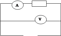
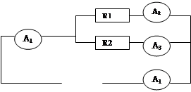
Fig.2. Kirchhoff's first law
| Observational data | Calculation results | |||
| R | U | I | E | |
| 1 | 3 | 3 | 3 | 3,3 |
| 1,5 | 3 | 2 | 3 | 3,2 |
| 3 | 3 | 1 | 3 | 3,1 |
| Observational data | Calculation results | |||||||
| 2 | 0,7 | 4 | 1 | 3 | 4 | 4 | 2 | 2,1 |
| 1 | 1 | 4 | 2 | 2 | 4 | 4 | 2 | 2 |
| 0,7 | 2 | 4 | 3 | 1 | 4 | 4 | 2,1 | 2 |
![]()
E 1 =3(1+0.1)=3.3; E 2 =2(1.5+0.1)=3.2; E 3 \u003d 1 (3 + 0.1) \u003d 3.1
![]()
U 1 \u003d 2 * 1 \u003d 2; U 2 \u003d 2 * 1 \u003d 2; U 1 \u003d 3 * 0.7 \u003d 2.1; U 2 \u003d 1 * 2 \u003d 2
It was proved experimentally and by calculation that the current strength in an electric circuit with one EMF is directly proportional to this EMF and inversely proportional to the sum of the resistances of the external and internal sections of the circuit. According to Kirchhoff's first law, the current at the input of the circuit is equal to the current at the input of the circuit. The sum of the currents on the branches of the circuit is equal to the current at the output of the circuit.
Answers to security questions
Ohm's law for a complete circuit considers the impedance of the entire circuit, and Ohm's law for a section of a circuit considers only this section of the circuit. Both Ohm's laws show the dependence of current on resistance - the greater the resistance, the lower the current and EMF, or vice versa.
To create voltage in the circuit, the movement of charges inside the current source is necessary, and this happens only under the action of forces applied from the outside. In the absence of current in the circuit, the EMF is equal to the potential difference of the energy source, therefore, a voltmeter connected to this circuit shows EMF, and not voltage.
I - Kirchhoff's law (used to calculate complex electrical circuits): the sum of the currents coming to the nodal point is equal to the sum of the currents leaving it, and the direction of the currents to the point is considered positive, and from it - negative. Or the algebraic sum of the currents at the nodal point of the electrical circuit is zero.
II - Kirchhoff's law (for any electrical circuit): the algebraic sum of all EMFs is equal to the algebraic sum of the resistance voltage drops connected in series.
E 1 + E 2 + ... + E n \u003d I 1 R 1 + I 2 R 2 + ... + I n R n
LAB #16
TESTING OHM'S LAW FOR AC
GOAL OF THE WORK: determine inductive and capacitive reactance, check Ohm's law for alternating current.
INSTRUMENTS AND ACCESSORIES: alternating voltage source, choke coil, capacitors, rheostat, AC milliammeters and voltmeters, connecting wires, key.
BRIEF THEORY
Ohm's law was established for direct current, but it remains true for instantaneous values of changing current and voltage, as long as their changes do not occur too quickly. Currents satisfying this condition are called quasi-stationary.
An alternating current is called quasi-stationary if, with a sufficient degree of accuracy, it can be assumed that the magnetic field of this current at each moment of time has the same values \u200b\u200bthat it has in the case of a direct current of the same magnitude.
The processes occurring in AC circuits are somewhat different from the processes observed in circuits direct current.
If to a circuit section containing only active resistance R o, an alternating voltage is applied:
U m - voltage amplitude;
- cyclic frequency,
then a current arises in this section, the instantaneous value of which is determined by the relation:
 ,
(2)
,
(2)
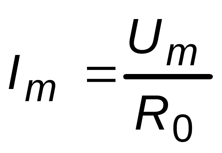 - current amplitude.
Equations (1) and (2) show that the phase of voltage and current is the same, i.e. voltage and current simultaneously reach maximum values and simultaneously turn to zero.
R 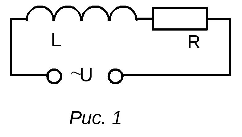 Consider an alternating current circuit that contains an inductor L and active resistance R(Fig. 1).
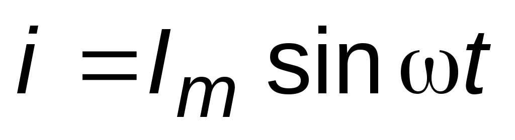
The variable EMF E will cause a sinusoidal current:
 . (3)
. (3)
When current flows through the coil, there is a voltage drop across the resistance U R, and at the ends of the coil, an EMF of self-induction occurs:
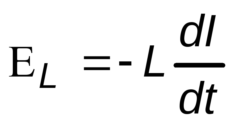 .
.
According to Kirchhoff's second law, the resulting external voltage in the circuit is determined by the sum U R and L, external emf is written in the following form:
 .
.
Differentiating this equation, we get:
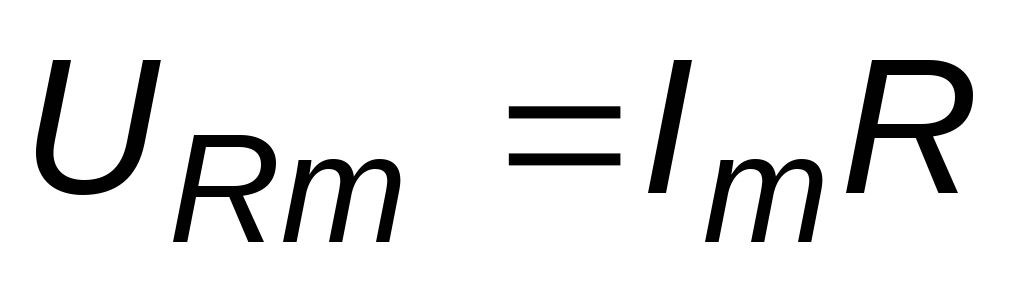 - the amplitude value of the voltage on the active resistance;
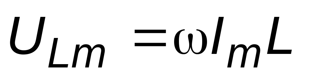 - the amplitude value of the voltage on the inductance.
From this it follows that L performs the function of resistance:
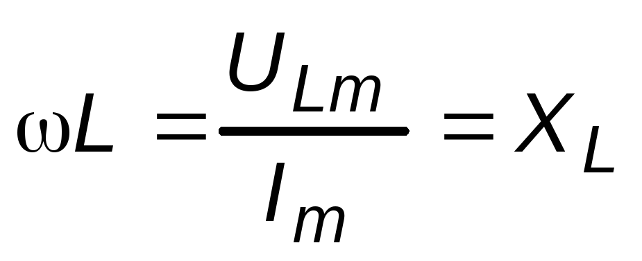 .
.
the value X L is called reactance.
Comparing expressions (3) and (4), we see that in the circuit under consideration, the change in current lags behind the change in voltage by an angle of 0.5.
The physical reason for the occurrence of this phase difference is as follows: if the active resistance of the circuit section is zero, then the applied voltage exactly balances the self-induction EMF and is equal to the latter with the opposite sign. But the EMF of self-induction is not proportional to the instantaneous value of the current, but to the speed of its change, which will be greatest at those moments when the current passes through zero. Therefore, the voltage peaks coincide with current zeros, and vice versa.
With 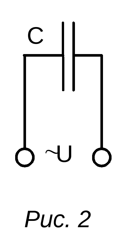 connect the plates of a capacitor having a capacitance C, to the source of alternating voltage (Fig. 2). The capacitor will begin to continuously recharge, and an alternating current will flow in the circuit:
. (5)
Since the current in the supply conductors is equal to:
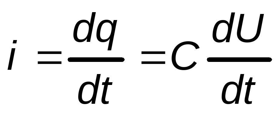 ,
,
then we get the differential equation:
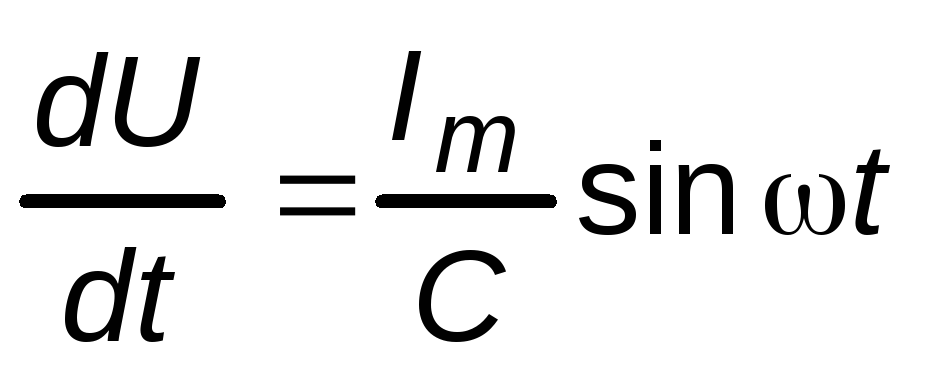 .
.
Taking into account the fact that there is no constant voltage source in the circuit, the solution to this equation has the form:
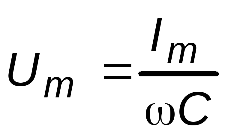 - the amplitude value of the voltage on the capacitor.
Value 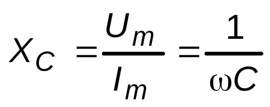 called capacitive reactance. Unlike active resistance, capacitance does not consume power on average, since the capacitor either takes energy from the circuit when charging, then gives it back to the circuit when discharging.
Comparing expressions (5) and (6), we see that the current phase leads the voltage phase by 0.5.
P 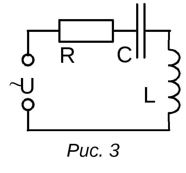 The appearance of a phase difference =0.5 between the voltage on the capacitor plates and the current through it is associated with the processes of charging and discharging the capacitor. If the current is zero with a fully charged capacitor, then there is a charge on the capacitor transferred by the current in the previous period of time, and the voltage on its plates reaches its maximum value. When the charge of the capacitor and, consequently, the voltage becomes equal to zero, the current has a maximum value.
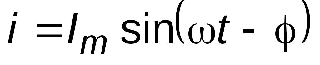
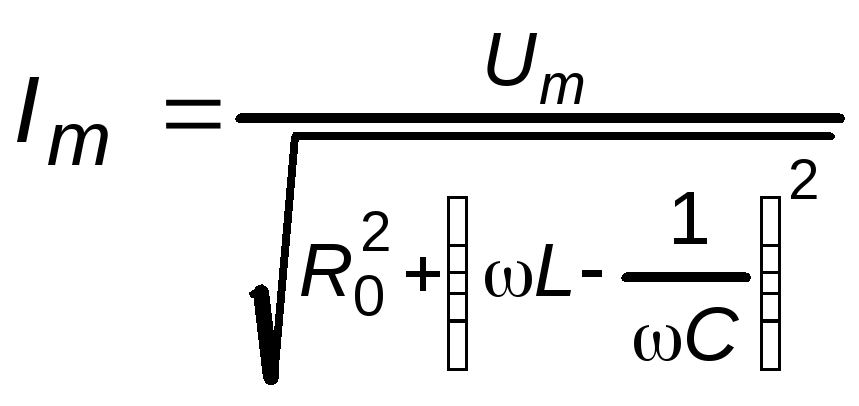
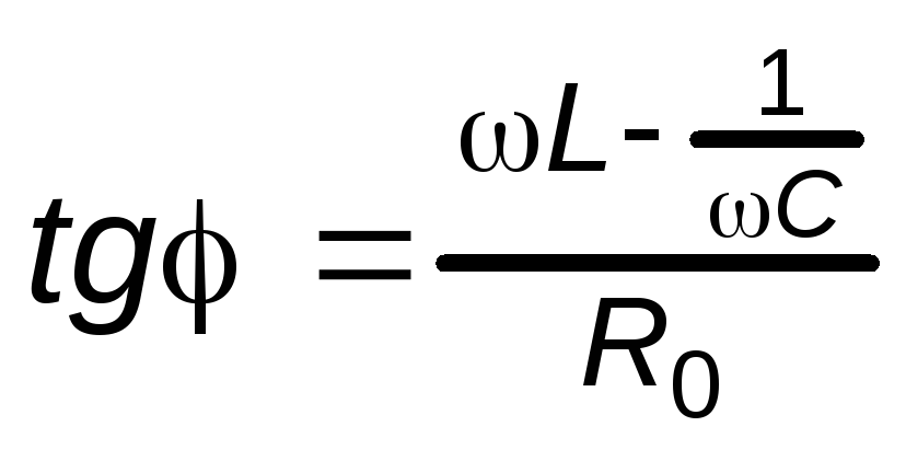
If in the area of active resistance R o a coil with an inductance is connected in series with it L and a capacitor With(Fig. 3), then a phase shift occurs between the current and voltage, the instantaneous value of the current will be expressed by the ratio:
 , (7)
, (7)
 ,
,
 .
.
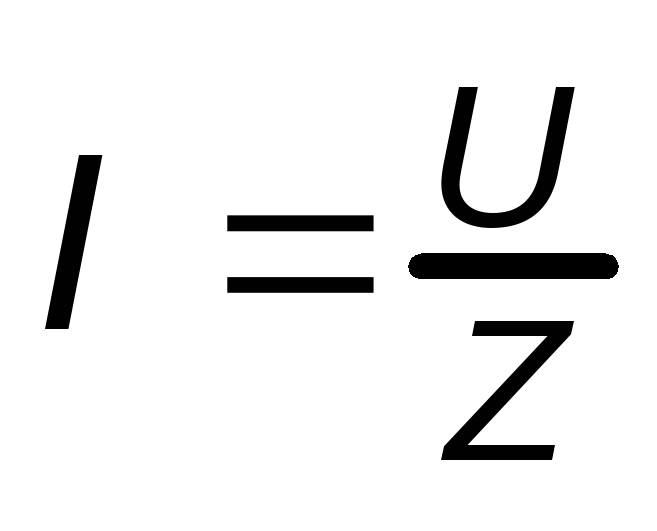
The ratio of the voltage amplitude to the current amplitude is called the impedance of the circuit for alternating current:
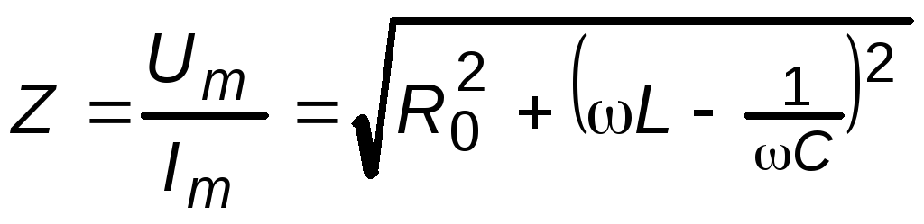 , (8)
, (8)
R 0 - active resistance,
 is the reactance of the circuit.
Instruments used in AC circuits measure effective value current and voltage, but since:
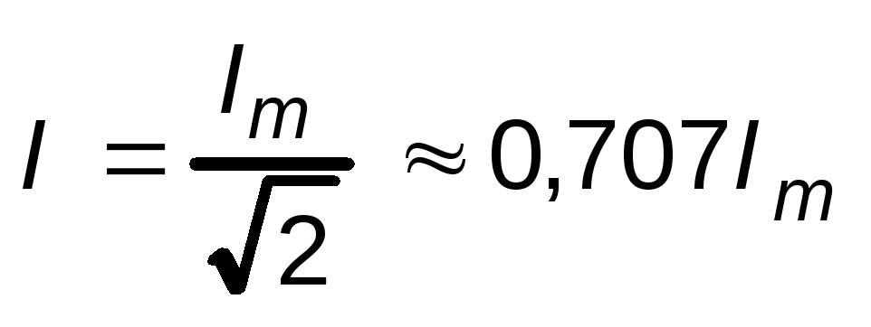 ;
;
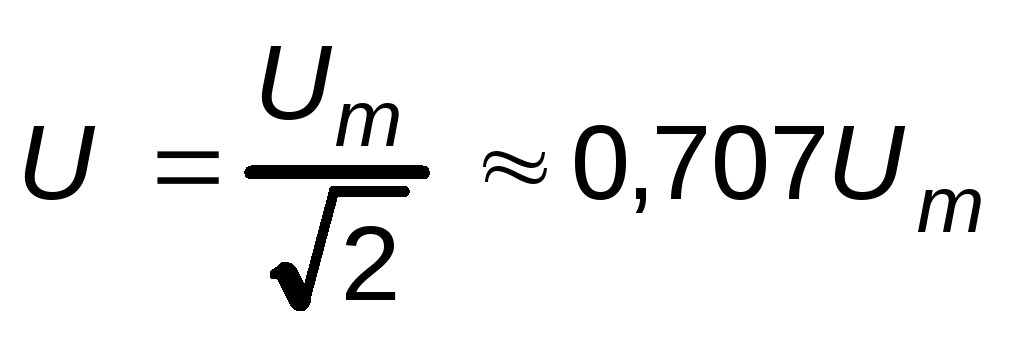 ,(9)
,(9)
then it is obvious that between the effective values of current and voltage, the same relationship is maintained as between the amplitude ones:
 .
.
working process
TASK 1. Measuring the inductance of coil sections.
Determine the active resistance of the coil section (see the description of the throttle coil).
Assemble the circuit according to the diagram in Fig. 4, where L- different sections of the coil.
Set the maximum resistance on the rheostat and turn on the AC voltage source.
For each section, measure the voltage at three currents. Record the data obtained in the table. one.
Determine the section resistance Z L and the inductance of the corresponding sections.
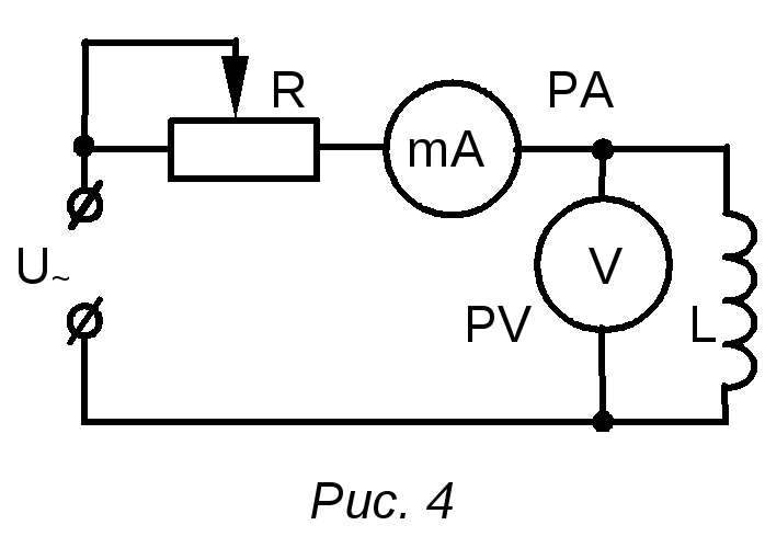
Table 1
|
Number of turns | ||||||
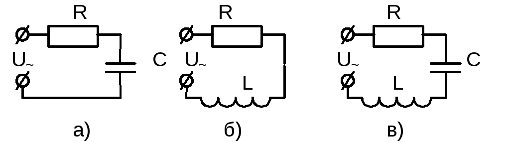
TASK 2. Determination of the capacitance of capacitors.
Assemble the circuit according to the diagram in Fig. 5 for capacitor C 1 .
Measure the voltage across the capacitor at three current values. Record the measurement results in table. 2.
Z Cav and calculate the capacitance of the capacitor. Record the results of the calculation in table. 2.
Repeat steps 1-3 for capacitor C 2.
Repeat steps 1-3 for series and parallel connections of capacitors C 1 and C 2.
Draw conclusions based on the results.
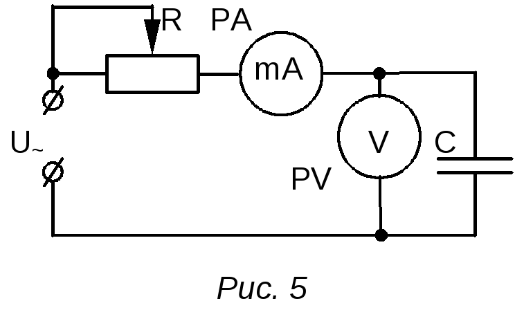
table 2
|
Connection diagram | ||||||
TASK 3. Checking Ohm's law for alternating current.
Assemble the circuit according to the diagram in Fig. 6.
Measure the voltage in the circuit section at three current values. Record the measurement results in table. 3.
Determine the average value of the section resistance Z ch.av.
Compare calculated by formula (8) Z calculated and measured Z measured mean resistance value. Record the results of the calculation in table. 3.
Draw conclusions based on the results.
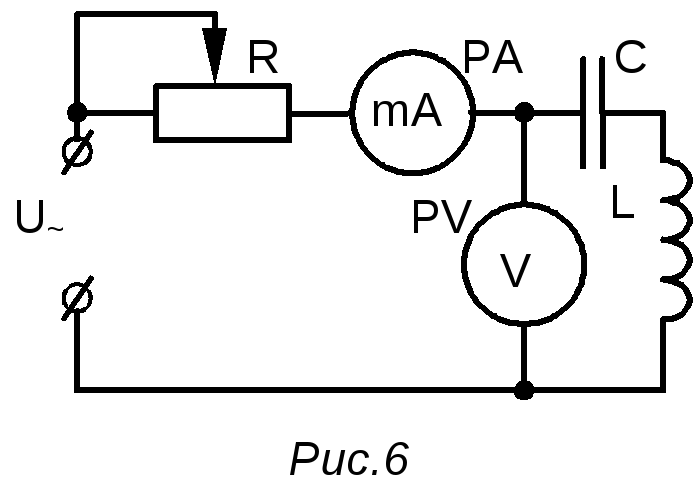
Table 3
|
Z meas.av, Ohm | ||||||||
TEST QUESTIONS.
Is it always possible to assert that ohmic and active resistances are equal to each other?
What is the cyclic frequency of the city power grid?
How to physically explain that the inductive reactance increases with increasing frequency, and the capacitive reactance decreases?
What will be the phase shift between current and voltage if the section contains only capacitance?
What will be the phase shift between current and voltage if the section contains only inductive reactance?
How is the total capacitance expressed when capacitors are connected in series and in parallel?
In what units must inductance and capacitance be expressed in order for impedance to be expressed in ohms?
Derive a formula for calculating the inductance according to table. one.
Derive a formula for calculating the capacitance according to Table. 2.
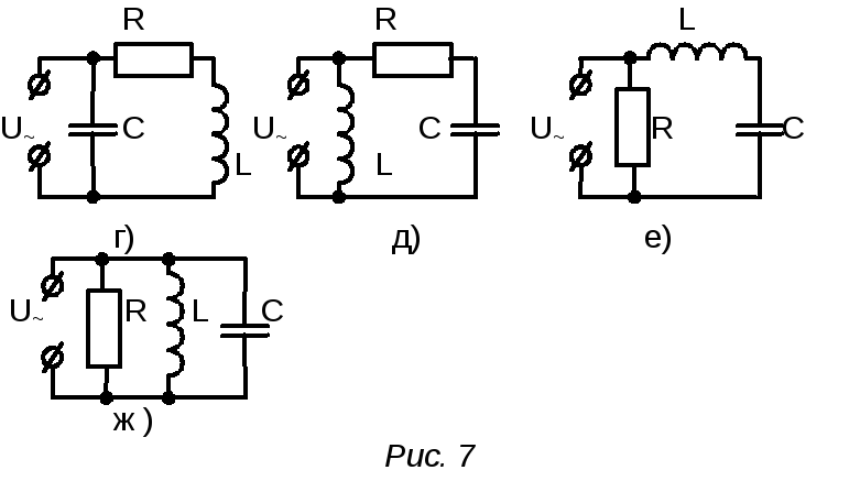
Draw vector diagrams for the following cases:
Alekseev O.L., Voronchikhin L.D., Kovrizhnykh Yu.T.. Guide to laboratory work on the course of general physics: Electricity. - Sverdlovsk, 1974. - p. 188-194.
Saveliev I.V.. Course of general physics. Electricity. - M.: Nauka, 1970. - T.II. - with. 343-346.
Evsyukov A.A.. Electrical Engineering: Proc. allowance for physics students. specialist. ped. in-comrade. - M .: Education, 1979. - p. 10-27.