DC to AC converters. How to make alternating current from direct current?
"Belorussian State University informatics and radio electronics”
Department of Information Security
« ELECTRICAL CONVERTERS »
inverter- Converts direct current to alternating current.
Converter- DC to DC converter, but of a different level (with intermediate conversion of the input voltage to AC and transformation to the desired level).
The central link is a DC-to-AC converter.
Various schemes of such devices are used:
Transistor and electronic tubes;
Built on transistors with saturable cores;
Relaxation generators, triggers, multivibrators;
According to single-stroke, two-stroke and bridge circuits;
Thyristor simple and bridge circuits (in powerful devices).
A simple circuit of a push-pull thyristor inverter
Figure 1 - a simple circuit of a push-pull thyristor inverter
From T2, control pulses are sent to the thyristor circuit.
From a constant source, voltage is supplied to the input of the circuit. It goes through
on VD anodes. charged to double the input voltage. If we now apply pulses to VD2, VD1 immediately closes, recharges, all signs in T1 will change to the opposite and the current will flow through VD2.As can be seen from the operation of the circuit, on the switching capacitance
at the moment of closing the thyristor, a voltage equal to twice the supply voltage acts, which is a disadvantage for the circuit.It is eliminated by the bridge circuit of the thyristor inverter.
Bridge circuit thyristor inverter
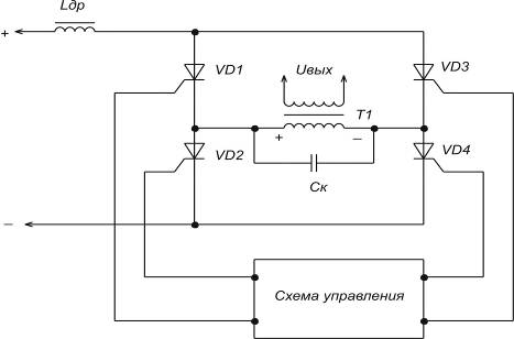
Figure 2 - Bridge circuit of a thyristor inverter
The control circuit first opens VD1 and VD4, and then, when the capacity is charged up to
, at this point, if you open other thyristors, VD1 and VD4 will instantly close.In this circuit, only the voltage of the power source acts on closed thyristors.
Thyristor rectifiers are efficient promising inverters. They are used at significant power and are currently used to replace electric machines that convert energy direct current backup batteries into alternating current, in uninterruptible power supply devices (UGP) of equipment at communication enterprises.
DC voltage converters
Often, when powering electronic devices, power supplies are low-voltage, and significant voltages are required to power consumption circuits. In this case, voltage conversion is used. To do this, use inverters and converters. Electromagnetic transducers, vibration transducers and static transducers are used on p / n devices.
Electromagnetic transducers generate a sinusoidal voltage, while semiconductor and vibration transducers produce a rectangular voltage. Currently, there are static converters with an output voltage close to sinusoidal in shape. The disadvantage of the electromagnetic converter: large dimensions and weight. Vibration transducers are low-power and unreliable. Therefore, semiconductor converters with small dimensions and weight, high efficiency and operational reliability are most widely used.
The construction of converters based on thyristors and transistors should be associated with the magnitude of the supply voltage, the required power, and the nature of the load change.
Transistor voltage converters
They are divided according to the method of excitation into 2 types: with self-excitation and converters with power amplification.
Transistors can be switched on according to the scheme with OE, OK, OB, but switching on with OE is most widely used, since in this case the maximum amplification of transistors in terms of power is realized and, moreover, self-excitation conditions are simply achieved.
Converters with self-excitation are carried out at powerful, up to several tens of watts, according to single-cycle and push-pull circuits. The simplest circuit single-ended converter is a relaxation oscillator with feedback.
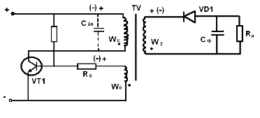
With reverse diode. With direct incl. diode.
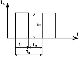
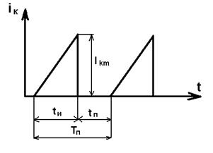
When the supply voltage is connected through a resistor, a reference potential is applied to the base of the transistor. The transistor opens and a current flows through the primary winding Wk of the transformer, which causes a magnetic flux in the magnetic circuits of the transistor. The voltage that appears on the winding Wk is transformed into the feedback winding Wb, the connection polarity of which is such that it contributes to unlocking the transistor. When the collector current reaches its maximum value: Ik \u003d Ib * h21e, the growth of the magnetic flux stops, the polarity of the voltages on the transformer windings changes to the opposite and an avalanche-like process of turning off the transistor occurs. The voltage on the secondary winding of the transformer has a rectangular shape.
The polarity of the rectifier power diode connected to the secondary side of the transformer determines how power is transferred to the load. The diode opens when the transistor closes, the capacitor is charged, which maintains a constant current in the load.
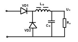
When the diode is directly turned on, the energy transfer of the power source Up to the load Rn occurs during the time period tu, when the transistor and the power diode VD1 are open. Energy is stored in the throttle W = 0.5 * Lf * In ^ 2 * tu. In this case, the smoothing filter capacitor Cf is charged by a rectified voltage up to Up.
During the pause tp, when the transistor is closed, the current circuit In is closed through the inductor Lf and the blocking diode VD2, as in switching regulator with sequential control.
In single-cycle converters, the transformer operates with bias, which can be overcome by using a core with a charge. However, it does not fit when using tor. transistor. In our case, a blocking capacitor is used, which, during a pause tp, is discharged through the winding W1, remagnetizing the core with the discharge current.
Capacity Cbl. It is selected from the condition that at the maximum duty cycle φmax, the duration of the pause tp is at least a quarter of the period of the oscillatory circuit L, Cbl.
Such a diode reverse converter provides decoupling and protection of the output voltage from noise on the input power rails.
Transistor converters are determined by the following formulas:
Up \u003d Up (Ikm / 2In-W1 / W2)
tu \u003d Ikm * L1 / Up
tp \u003d Ikm * L2 / Un * W2
φ = fp*Ikm*L1/Up = tu/(tu+tp)
The best weight and size indicators have push-pull converters with a step-down transformer.
Transformers are made on a magnetic circuit with a rectangular hysteresis loop. Positive OS is also used here. The generator works as follows. When the supply voltage Up is turned on, due to the non-identity of the parameters, one of the transistors, for example VT1, starts to open and its collector current increases. The windings of the OS Wb are connected so that the EMF induced in them completely opens the transistor VT1 and closes the transistor VT2.
Switching of transistors begins at the moment of saturation of the transistor. As a result, the transformers induced in all windings. The voltages decrease to zero and then reverse their polarity.
Now, a negative voltage is applied to the base of the previously open transistor VT1, and a positive voltage is supplied to the base of the previously closed transistor VT2 and it starts to open. This regenerative process of forming the front of the output voltage is very fast. In the future, the processes in the scheme are repeated.
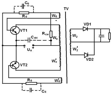 The switching frequency depends on the value of the supply voltage, the parameters of the transformer and transistors and is calculated by the formula: fp \u003d ((Up-Uke us) * 10000) / 4 * B * s * Wk * Sc * Kc.
 This mode is more economical than when switching due to the limiting collector current and the operation of the converter is more stable.
Such converters are used as master oscillators for power amplifiers and as autonomous low-power power supplies. Main advantages: simplicity of the circuit, as well as insensitivity to a short circuit in the load circuit.
The disadvantage of a converter with a saturable core is the presence of collector current surges at the moment of transistor switching, which increases the losses in the converter.
The voltage across the closed transistor can reach the value:
Uкem \u003d (2.2: 2.4) Upmax
two voltages is the sum of Up + EMF on the idle winding, in addition, voltage surges during switching are taken into account. To reduce the latter, shunt diodes are sometimes included in the circuit.
When converting high powers, converters using a power amplifier are most widely used. Self-excited converters can be used as master oscillator. The use of such converters is advisable if it is necessary to ensure the constancy of the frequency and voltage at the output, as well as the invariance of the shape of the AC voltage curve when the load of the converter changes.
In the case of high input voltage, bridge power amplifiers are used.
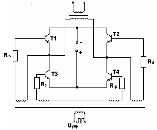 Let's assume that transistors T1, T2 work simultaneously in the first half-cycle. In the second T2, T3. The supply voltage is applied to the primary winding of the transistor, its polarity changes every half cycle. The voltage across the closed transistor is equal to the voltage of the power supply. The output transistor operates in an unsaturated mode, it is made of a material with a non-rectangular hysteresis loop.
 Thyristor converters
Thyristors, unlike transistors, have one-way control. To lock thyristors in converter circuits, reactive elements are used mainly in the form of switching capacitors.
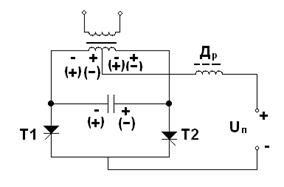 When the first thyristor is unlocked, the capacitance is charged to a voltage of 2Up. When the second thyristor is unlocked, the capacitor voltage is applied in the opposite direction to the first transistor, under the action of which it is locked. The capacitor is recharged, and the voltage on its windings and on the primary winding of the thyristor changes sign (the potentials are shown in brackets in the diagram). In the next half-cycle, the thyristor T1 is again unlocked and the process is repeated.
 To ensure the locking of thyristors, it is necessary that the energy of the switching capacitor be sufficient so that during the recharging process, the reverse voltage across the thyristors falls slowly enough to ensure the restoration of their locking properties.
The disadvantage of such an inverter is the strong dependence of the output voltage on the load current.
To reduce the influence of the nature and magnitude of the load on the shape and magnitude of the output voltage, circuits with reverse diodes are used, which, in turn, are necessary to return the reactive energy accumulated in the inductive load and reactive switching elements in the power supply of the converter.
Power supply with transformerless input
A feature of such sources is the use of the input voltage conversion process using a high frequency.
The absence of a power transistor at the input and the use of transistors increased frequency significantly improves the weight and size characteristics.
The functional diagram of the IPBV based on an adjustable converter has the following form:
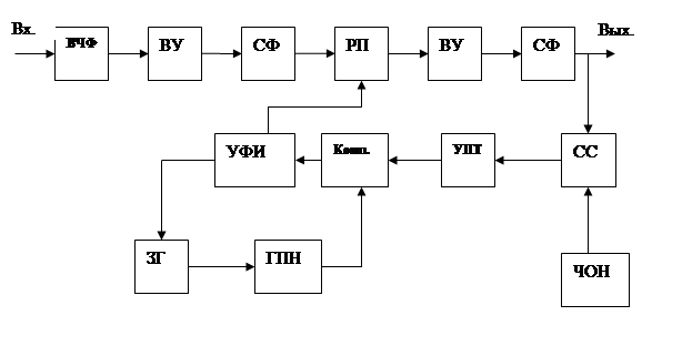
VChF - prevents penetration into the input circuits of interference from IPBV and vice versa.
VU - rectifier,
SF - smoothing filter;
RP - adjustable transducer;
ZG - synchronizing master oscillator;
GPN - sawtooth voltage generator.
The operation of the IPBV with input voltage stabilization using PWM is easy to imagine by considering the voltage diagrams in individual sections of the circuit.
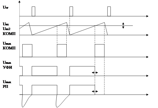
In order to simplify the adjustment, the converter is usually built according to a single-cycle circuit with the recuperation of part of the energy accumulated in the reactive elements to the input voltage source. At the output of the converter at voltages of 5 - 10V, a rectifier with a midpoint is placed. In order to reduce the switching time of power transistors, circuits are used at their inputs that provide a significant excess of the blocking voltage with respect to the negative one.
LITERATURE
1. Ivanov-Tsyganov A.I. Electrotechnical devices of radio systems: Textbook. - Ed. 3rd, revised. and add.-Mn: Higher School, 200
2. Alekseev O.V., Kitaev V.E., Shikhin A.Ya. Electrical Devices / Ed. A.Ya. Shikhina: Textbook. – M.: Energoizdat, 200–336 p.
3. Berezin O.K., Kostikov V.G., Shakhnov V.A. power supply sources of radio-electronic equipment. – M.: Tri L, 2000. – 400 p.
4. Shustov M.A. Practical circuitry. Power supplies and stabilizers. Book. 2. - M.: Alteks a, 2002. -191 p.
All of you probably wondered: "How to get a constant voltage from an alternating one?" Well, I think it's time to reveal this secret :-), although you can't call it a secret. In this article, I'll show you the basics, and it's up to you to decide how much voltage to get. It turns out that this is actually much easier than it seems.
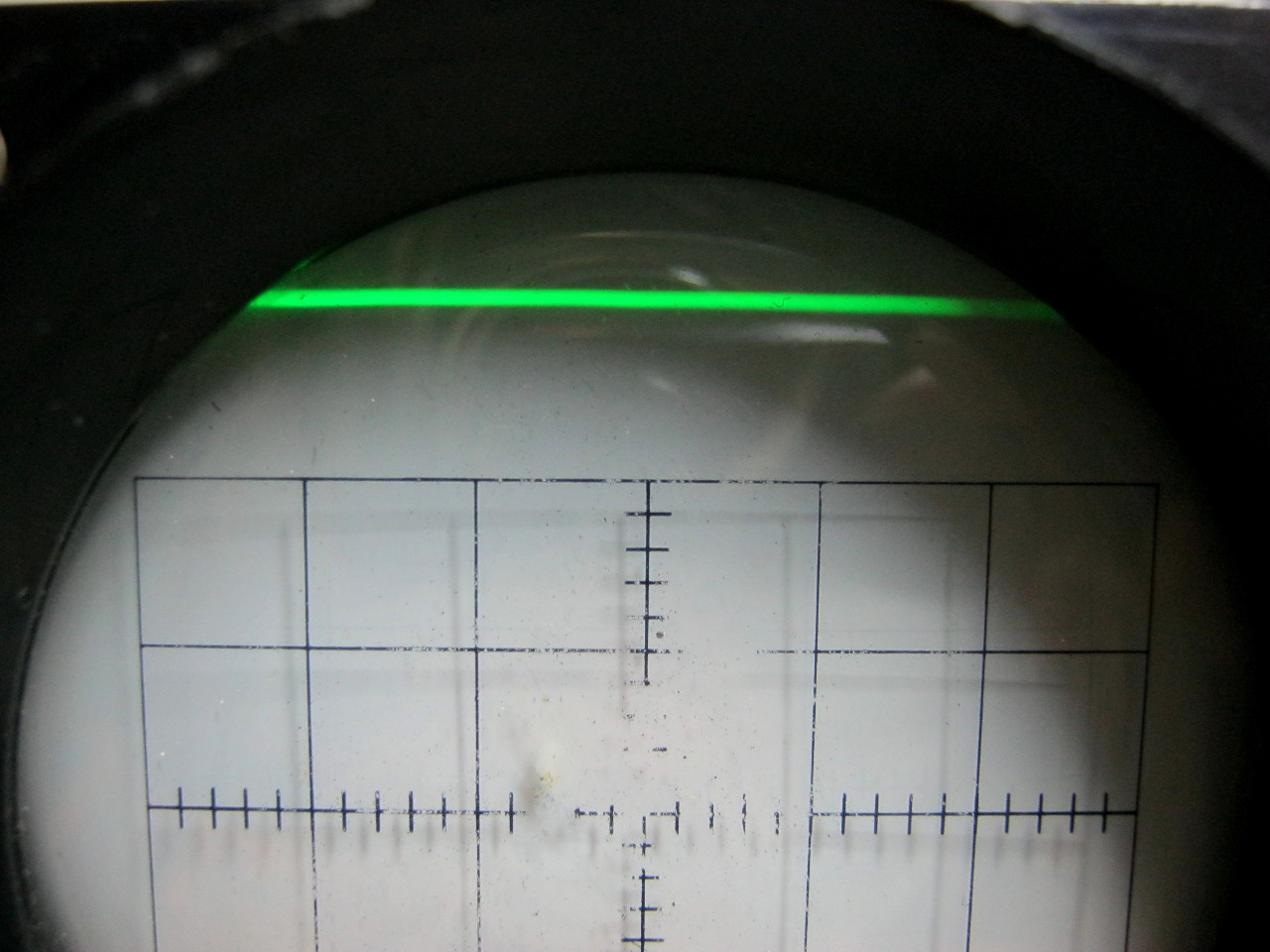
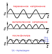
Let's first clarify what we mean by "constant voltage". As Wikipedia tells us, direct voltage (it is also direct current) is such a current, the parameters, properties and direction of which do not change with time. Direct current flows in only one direction and for it the frequency is zero. We discussed the DC oscillogram in the Oscilloscope article. Fundamentals of Operation. And here is the DC voltage waveform itself:
As you remember, horizontally on the chart we have time(X-axis), and vertically voltage(Y axis).
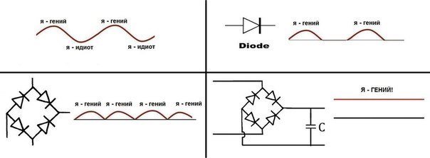
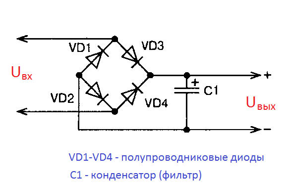
In order to convert a single-phase alternating voltage of one value into a single-phase alternating voltage of a smaller (possibly larger) value, we use a simple single-phase transformer. And in order to convert into a constant pulsating voltage, after the transformer, we connected the Diode bridge. The output received a constant pulsating voltage. But with such tension, as they say, you can't change the weather.
But what about us from a pulsating constant voltage
get the most real constant voltage?
To do this, we need only one radio component: capacitor. And this is how it should be connected to the diode bridge:
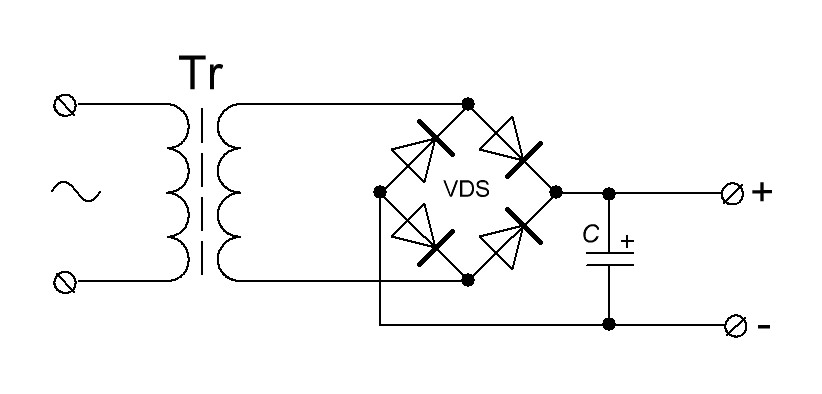
This circuit uses an important property of the conder: to charge and discharge. The whole joke is that the conder with a small capacity is quickly charged and quickly discharged. Therefore, in order to get an almost straight line on the oscillator, we must insert a decent capacitor.
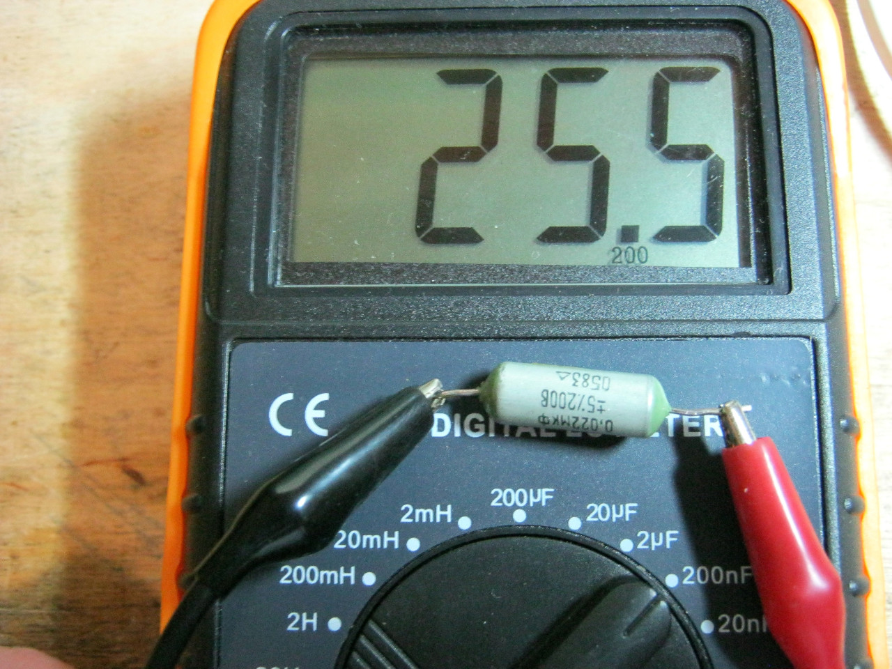
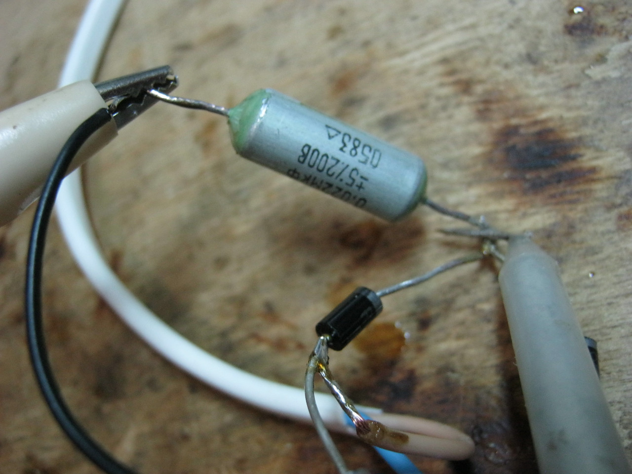
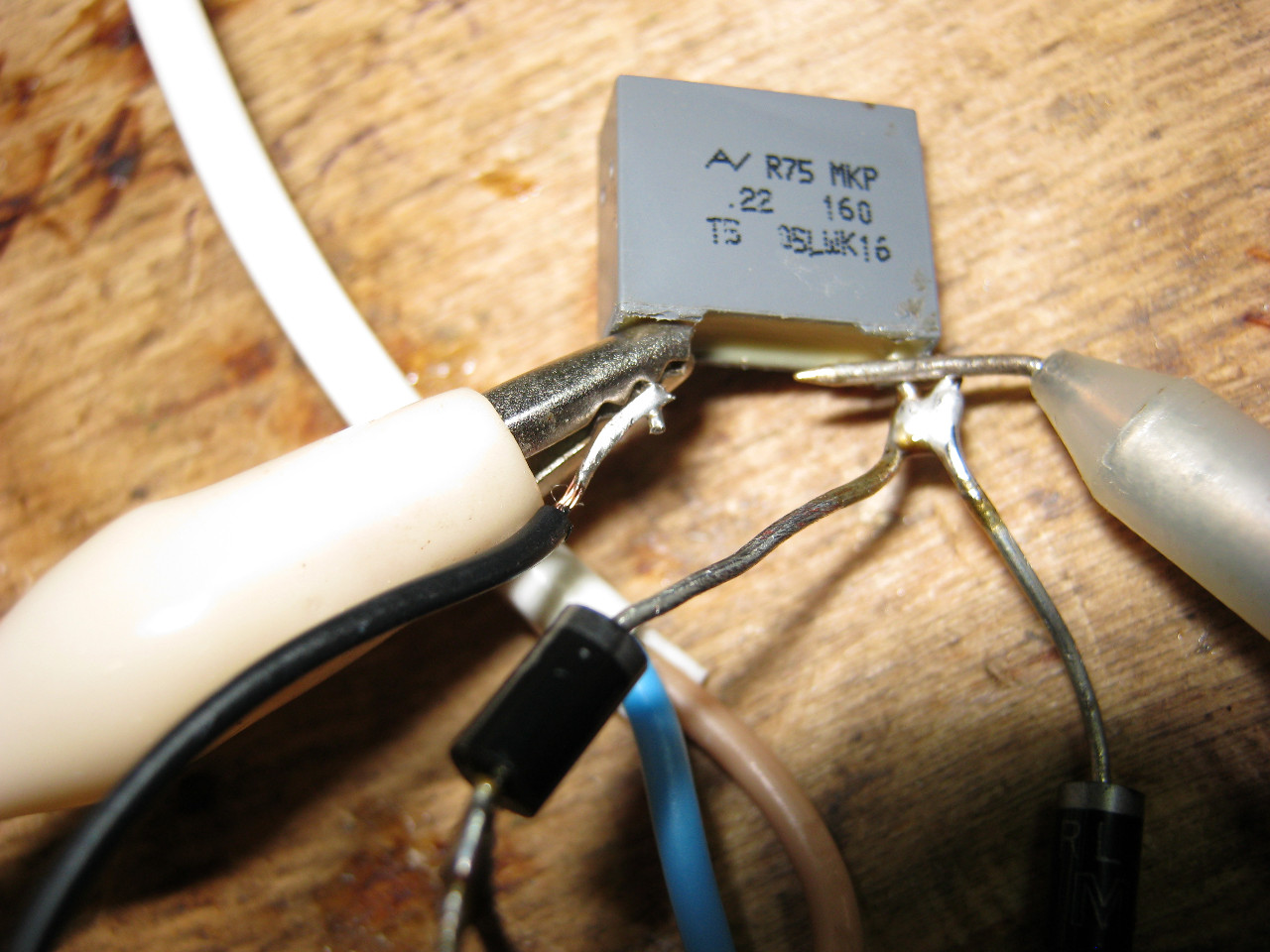
Let's see in practice why we need to install a high-capacity conder. In the photo below we have three conders. All different capacities.
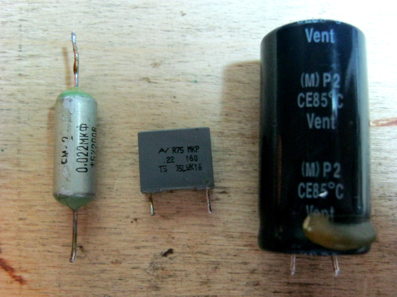
Let's consider the first conder. We measure its face value using our LC - meter . Its capacitance is 25.5 nanofarads or 0.025 microfarads.
We cling it to the diode bridge according to the scheme above
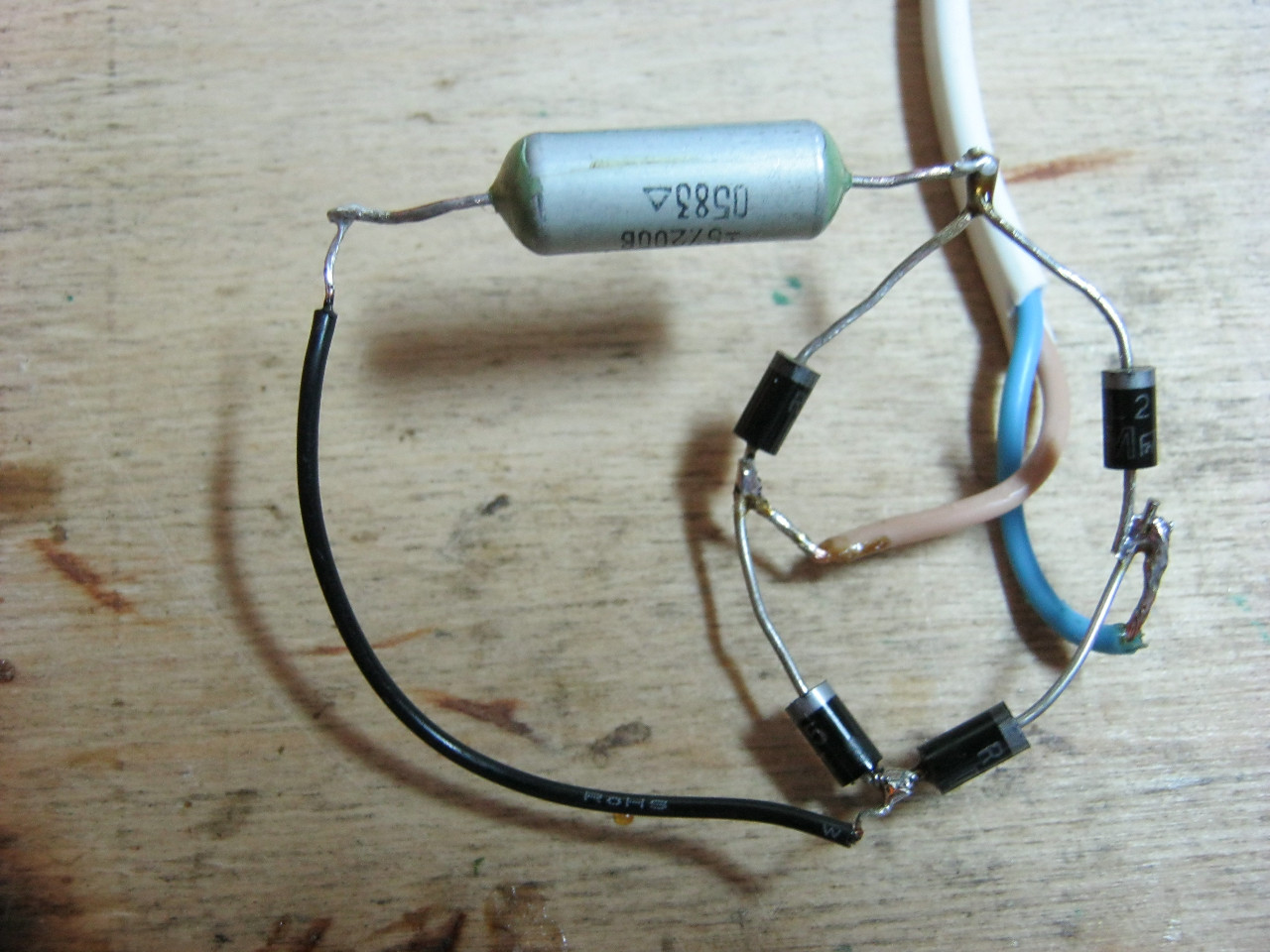
And we take readings from the conder with an oscil.
And here is the oscillogram from the conder.
Noooo... that's not a DC waveform. The pulsations are still there.
Well, let's take a larger capacity conder.
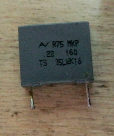
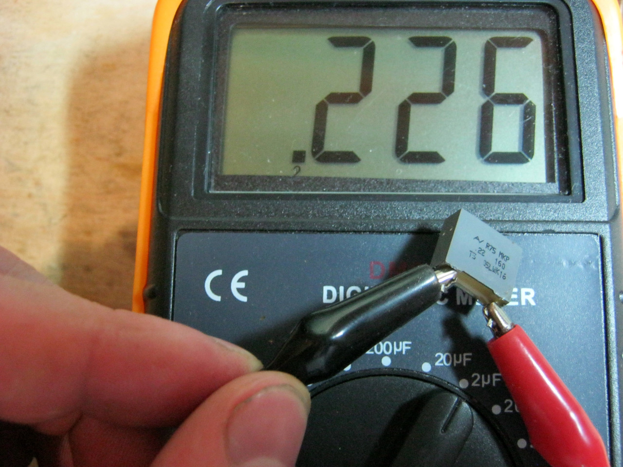
We measure its capacity. It turns out 0.226 microfarads.
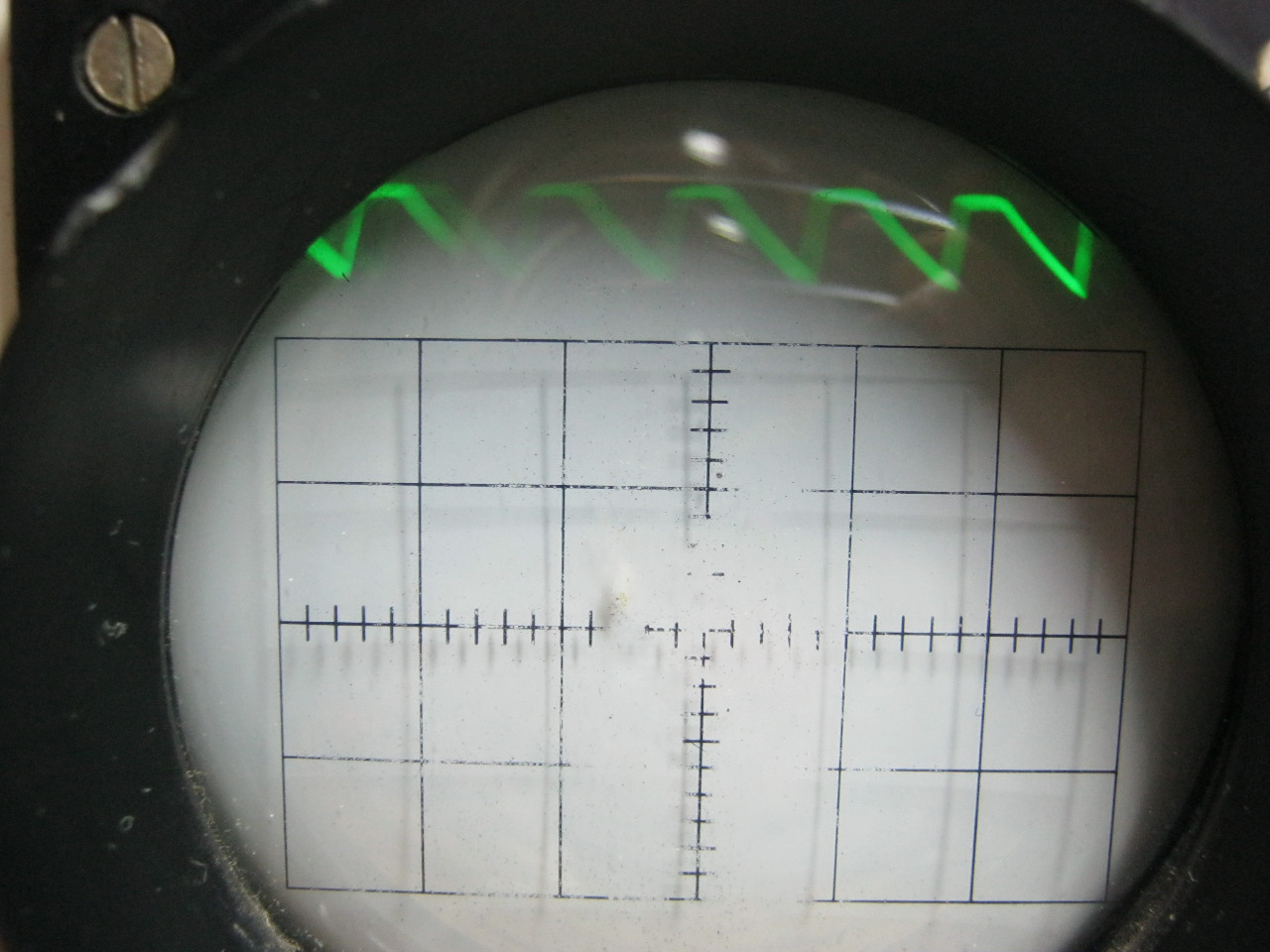
We cling to the diode bridge in the same way as the first conder, we take readings from it.
And here is the oscillogram itself.
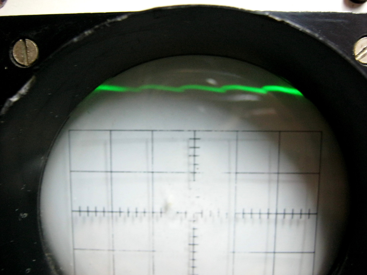
Not ... almost, but still not the same.
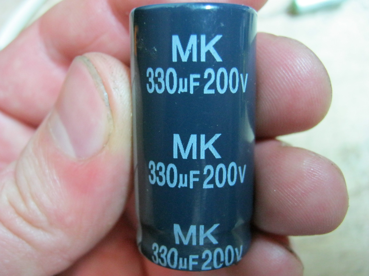
We take our third conder. Its capacitance is 330 microfarads. Even my LC meter will not be able to measure it, since I have a limit on it of 200 microfarads.
We hook it to the diode bridge and take an oscillogram from it.
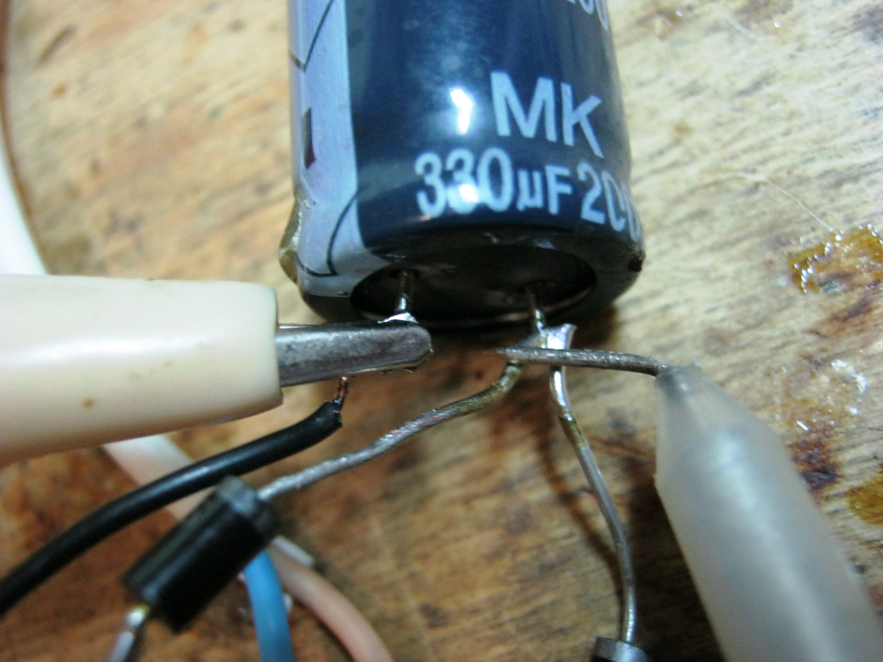
And here she is
Well. It's quite another matter!
So, let's make some conclusions:
The larger the capacitance at the output of the circuit, the better. But do not abuse the capacity! Since in this case our device will be very large, because capacitors of large capacities are usually very large.
The lower the load at the output of such a power supply, the greater the ripple amplitude will be. In this case, it is best to use three-terminal voltage regulators, which produce the purest DC voltage.
Let's return to our question at the beginning of the article. How to get a constant current of 12 volts at the output, say, for some trinkets? First you need to pick up a trance so that it gives out ... 12 volts at the output? But they didn't guess! From the secondary winding of the trance, we will receive the operating voltage.

where
U D- operating voltage
Umax- maximum voltage
Therefore, in order to get 12 volts of constant voltage, the output of the trance must be 12 / 1.41 = 8.5 volts. Now here is the order. In order to get such a voltage on the trance, we must add or subtract trance windings. Formula. Then we select diodes. We select diodes based on what we are going to power and what voltage and current should pass through the diodes. We are looking for suitable diodes according to datasheets (technical descriptions for radio elements). We insert a conder with a large capacity. We select the conder based on the fact that the voltage on it does not exceed that which is written on its marking. The simplest constant voltage source is ready to use!
By the way, I got a 17 Volt constant voltage source, since the trance has 12 Volts at the output (multiply 12 by 1.41).
And finally, to better remember ;-)
We read this article without fail.
Author: elremont from 22-08-2013In this guide, I'm going to cover silicon diodes, diode bridges, and how to convert AC to DC. This is a symbol of the diode and pictures. The stripe at the end of a diode tells you how to put it in your circuit, but what is a diode?
A diode is a device that allows current to flow in only one direction. This is handy to remember when comparing diodes to faucets that only allow water to flow in one direction. So if you run AC voltage or current through a diode, the negative voltage will be blocked and you will be left with only a positive half wave. This process is called current rectification... it doesn't just work with sine waves. This will also work with square waves, triangle waves, or any other waveform that has a negative half cycle. Wait a minute...
If you increase and superimpose the signals on each other, you can see that the voltage has decreased! This is because there is no such thing as a perfect diode. All diodes have a forward voltage drop, denoted by "Vf". This means that whenever current flows forward through the diode, there will be a voltage drop, which is typically around 0.7 volts. The exact value depends on temperature, current and type of diode, but for now let's just assume it's 0.7V So a silicon diode won't even turn on until there's 0.7V across its terminals and there will always be a 0.7V voltage drop across the diode after it's turned on. Test it experimentally to see what I mean: With a negative input voltage, the diode can't turn on, so you don't get anything at the output. 0.3 volts at the input is still not enough to open the diode, so again you get nothing. 0.9 volts at the input is enough to open the diode, but due to the voltage drop, you will only have 0.2V left. And at 10 volts, minus 0.7 volts, you get 9.3 volts.
Sometimes the voltage drop across the diode is a problem... sometimes it isn't... As an example, I'll show you that at 10 volts peak-to-peak at the input, it's almost imperceptible.
But if I try to rectify a 0.5V current like the signal coming from my MP3 player, the 0.7V drop becomes a problem and it doesn't work. To cope with this problem, one must use advanced technologies such as super diodes. But on this moment you don't need to worry about it. No device is 100% efficient, so let's talk about power. Will the diode heat up, can you predict? Well, the power loss in a diode is determined by Vf and the current flowing through the diode. For a typical silicon diode with Vf = 0.7 V, when passing one milliamp, only 0.7 mW is lost to heat, so this is not a problem. But already at 3 A, 2.1 W of heat is generated, which is quite a lot, so you will have to use a larger diode or use a diode with a low forward voltage drop, such as a Schottky diode. I will cover them in another video. Incidentally, no matter what anyone tells you, diodes in parallel will not be able to carry more current.
What happens if one diode closes? The heat that was generated on it will be released on other diodes. Old diodes are not perfect, but I want to talk about switching high speed diodes. I'm using 1N4007 diodes, they are designed for power electronics with low frequency AC 50 - 60 Hz, like in your house.
Now let's see what happens when I increase the frequency. After about 15 kHz, the diode becomes useless as it begins to conduct in the opposite direction. This is because it takes a certain amount of time for a diode to switch between open, allowing current to move forward, and closed. Different diodes will have different switching speeds. So, if I replace the 1N4007 with 1N4148, it will work well, up to 100 kHz and even more. To work with radio frequencies, you need to use diodes that switch even faster. Therefore, when you design something, you should think about the maximum reverse voltage of your diode, forward voltage, current rating and switching speed. Google will always help you in your search background information by diodes. It is good that in most cases it is not necessary to know the theory of how diodes work. So let's use diodes to build something. The most common use of diodes is to convert AC to DC, to power various devices that you have at home. I'm going to show you how to build a simple unregulated DC power supply very similar to this one. I'll start with a low current and then I'll show you how to improve the design to handle a larger load. We start by converting the mains voltage to a lower, safe AC voltage. I'll show you how to do it in my Transformers guide. With no load, my transformer gives me a nice clean sine wave of about 39 volts peak-to-peak at 60 Hz. I installed a 1N4007 diode and measured the voltage before and after the diode, you can see the negative voltage cut off. Technically I converted AC to DC with only one diode because I removed all the negative voltage. But that's not a very good DC, is it? Half the time you have a weird voltage hump and half the time we have nothing at all.
If you need a little more stability to power your payload, we'll add a capacitor to set things right. I start with 1uF, but the more capacitance the better because you will have more energy storage. This is more like the truth! I now have an ideal 18.7 volt DC supply. Whenever you make a constant voltage power supply, the best thing you can see on an oscilloscope screen is a constant constant voltage. Unfortunately, the only reason why everything looks perfect now is only because I didn't have time to connect the load. The capacitor is charging through the diode and there is nothing now to discharge the capacitor. So let's see what happens when I add a 4.7 kΩ resistor as a load. Ohm's Law predicts that there should only be 4 mA of load (which is very small), but look what happens. You see here that when the input voltage is positive, the diode allows current to flow, thus charging the capacitor. But as soon as the input voltage goes negative, the diode blocks the reverse flow of current and the only source of energy is the 1uF capacitor. And as you can see, its energy is quickly consumed even at low load. So what are we to do about it? Let's increase the size of our energy reservoir so that it is large enough to keep us powered until the next positive half wave. Let's replace the tiny 1uF capacitor with a large 470uF capacitor and see what happens.
It works very well! We now have a DC power supply that can deliver several milliamps of current, which is enough to power some sensors and op amps. Okay, let's upgrade it up a notch. With a load of ten ohms, this circuit should draw much more current. Well, what the heck... we're back to the situation where the voltage sags in every beat. The average voltage is 8 volts, with a current of about 0.8 amperes, but the magnitude of the voltage ripple is huge. Imagine if we try to connect something to these... the voltage will constantly drop so low that it will never stay constant! So even 470 uF as an energy storage device is no longer enough. We can try to solve the problem head-on and add even more capacity.
So let's see how the circuit works with 3400uF. Well... that's better... Now we got an average voltage of about 12.5 volts with a current of about 1.25 A, but we see 5 volt AC ripples, which is a lot. You can keep adding capacitance indefinitely to reduce the amount of sag between cycles. But for a load of several amps, this becomes impractical and expensive. But there is a little trick. If we take four diodes and arrange them in this way, we get a "diode bridge". Here's how it works: In the first half of the sine wave, a positive sine wave arrives on the top wire, these two diodes turn on and let current through. Next, the diodes close, blocking any possible changes in the direction of the current. Now in the second half of the sine wave, where the top wire becomes negative with respect to the bottom wire, the other two diodes turn on and the other two turn off. So instead of losing the bottom half of the AC waveform by cutting it off and never using it, you just flip it and re-route it. And at the output you get a constant current with ripples of 120 Hz instead of 60 Hz.
And just like before, you can process the output signal with capacitors to get a nice smooth voltage. You can buy ready-made bridge rectifiers, but they are easy to build yourself. Here is my bridge rectifier connected to the transformer. I made it with four 1N4007 diodes and I spent about 4 cents on them. Take a look at how the voltage changes from positive to negative at 60 Hz, and now it never goes below zero volts, and we get these positive constant voltage half-waves at 120 Hz. This is called full rectification because we are using both AC waves. Now let's go back to our ten ohm breadboard and see how the bridge rectifier performs at 470uF compared to the single diode we tested earlier.
Now we have an average of 11.6 volts instead of 8 volts, which we used to get from one diode. And you can see that this is because the bridge rectifier charges the capacitor twice as often because we are using both half-waves of the 60Hz AC mains. Now think about how much of a difference that is, given that these extra diodes only cost me three cents.
Bridge rectifiers can be a little hard to understand, but because they work so well, everyone uses them. Now let's compare one diode with 3400uF and a bridge rectifier with 3400uF. Now we are averaging 13.5 volts instead of 12.5 volts and we only have about one or two volts of ripple. In other words, the combination of a large capacity bridge rectifier can convert a large AC supply current into a large usable DC supply current. Just keep in mind that your diodes and capacitors must be rated for the voltage you are working with.
What we have now is basically what's inside those cheap little unregulated AC-to-DC power supplies that power radios, clocks, and other household gadgets. We could make a 9 volt version and it could power old Sega or Nintendo. But I want to emphasize that these are all unregulated power supplies. This means that even if we successfully smooth out the voltage ripple, we will still face the problem of changing the average voltage under load.
With no load, it's 18.7 volts. And with 1 ampere load, you will get 13 volts. For some circuits this won't matter if they are designed to handle a wide range of voltages. But many devices such as microcontrollers and other digital electronics will require a very stable voltage source, and for this you will need to create a so-called regulated voltage source. I will talk about voltage regulators in another video. Now you know what diodes do and how they convert AC to DC.
_
Electric current flows in various media: metals, semiconductors, liquids and gases. However, it can be constant or variable. In the article, we will consider separately direct and alternating current, as well as the conversion of alternating current to direct current.
Direct current and its sources
For direct current, the magnitude and direction do not change over time. On modern devices, it is indicated by the letters DC- short for English direct current(in literal translation - direct current). Its graphic designation:
DC sources are batteries and accumulators. All semiconductor electronic devices work on it: mobile phones, computers, TVs, satellite systems. To power these devices from the AC mains, they include power supplies. They lower the mains voltage to the desired value and convert alternating current to direct current. Charging device for batteries are also powered by AC and perform the same functions as power supplies.
Alternating current and its parameters
For alternating current, direction and magnitude change cyclically in time. The cycle of one complete change (oscillation) is called period (T), and its reciprocal is frequency (f). Letter designation of alternating current - AC, short for Alternating Current(alternating current), and graphically it is indicated by a segment of a sinusoid:
 ̴
̴
After this sign, the voltage is indicated, sometimes the frequency and number of phases.
Alternating current is characterized by the parameters:
| Characteristic | Designation | unit of measurement | Description |
| Number of phases | single phase | ||
| three-phase | |||
| Voltage | U | volt | Instant value |
| Peak value | |||
| effective value | |||
| phase | |||
| Linear | |||
| Period | T | second | Time of one full oscillation |
| Frequency | f | hertz | Number of vibrations in 1 second |
Single-phase current in its pure form is obtained using gasoline and diesel generators. In other cases, it is part of a three-phase, which is three voltages that change according to a sinusoidal law, uniformly shifted relative to each other. This time shift is called the phase shift angle and is 1/3T.
Four wires are used to transmit three-phase voltages. One is their common point and is called zero (N), and the other three are called phases (L1, L2, L3).
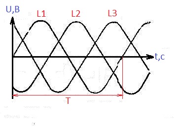
The voltage between phases is called linear, and between phase and zero - phase, it is √3 times less than the linear one. In our network, the phase voltage is 220 V, and the linear voltage is 380 V.
Under instant the value of the alternating current voltage is understood as its value at a certain point in time t. It changes with frequency f. The instantaneous value of the voltage at the maximum point is called amplitude value. But it is not measured by voltmeters and multimeters. They show a value √2 times smaller, called effective or effective voltage value. Physically, this means that a DC voltage of this magnitude will do the same work as the measured AC voltage.
Advantages and disadvantages of alternating voltage
So why did they choose alternating current and not direct current for power supply?
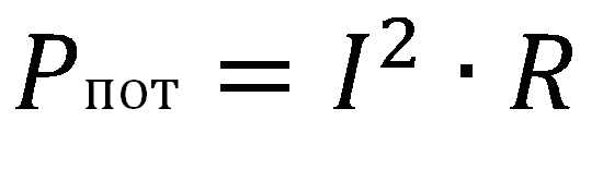
During the transmission of electricity, the current passes through wires hundreds of kilometers long, heating them and dissipating energy in the air. This is inevitable for both direct and alternating currents. But the power loss depends only on the resistance of the wires and the current in them:
The power transmitted through the line is:
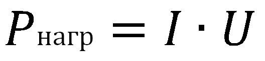
It follows that as the voltage increases, less current is needed to transmit the same power, and the power loss decreases. That is why extended power lines increase the voltage. There are lines for 6kV, 10kV, 35kV, 110kV, 220kV, 330kV, 500kV, 750kV and even 1150kV.
But in the process of transmitting electricity from a source to a consumer, the voltage must be repeatedly changed. It is easier to do this on alternating current using transformers.
Disadvantages of alternating current are manifested in the transmission of energy through cable lines. Cables have capacitance between phases and with respect to earth, and capacitance conducts alternating current. A leak appears, heating the insulation and disabling it over time.
AC to DC conversion and vice versa
The process of converting alternating current to direct current is called straightening, and the devices rectifiers. The main part of the rectifier - semiconductor diode that conducts current in one direction only. As a result of rectification, a pulsating current is obtained, which changes its value over time, but does not change sign.
Then the pulsations are eliminated with filters, the simplest of which is capacitor. It is impossible to completely eliminate ripples, and their final level depends on the rectifier circuit and the quality of the filter. The complexity and cost of rectifiers depends on the magnitude of the output ripple and on the maximum output power.
For conversion to alternating current, inverters. The principle of their operation is to generate an alternating voltage with a shape as close as possible to a sinusoidal one. An example of such a device is a car inverter for connecting household appliances or tools to the on-board network.
The better and more expensive the inverter, the greater its power or the more accurately the voltage it produces approaches a sinusoid.
1.3. AC conversion
to constant and constant to variable
Electricity is generated at power plants by synchronous generators, i.e., alternating current generators, which are conveniently converted by transformers and transmitted over long distances. Meanwhile, there are a number technological processes that require direct current: electrolysis, battery charging, etc. Therefore, it often becomes necessary to convert alternating current to direct current and vice versa.

Widespread at the beginning of the 20th century. electric machine converters (single-arm converters and motor-generator sets) have given way to more compact and noiseless semiconductor rectifiers. Thanks to high
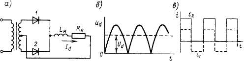
Rice. 1.12. Two-stroke single-phase rectifier
performance and small dimensions of semiconductor rectifiers, there is a tendency to replace DC generators with synchronous generators having a semiconductor rectifier at the output. Thus, new classes of machines appeared - transformers and synchronous - constantly working with rectifiers. However, the operation of an electric machine for a rectifier has features that must be taken into account when designing these machines and analyzing the processes occurring in them.
AC conversion in constant produced with the help of semiconductor valves having one-way conduction. On fig. 1.12 and 1.13 shows the most common rectifier circuits: single-phase (Fig. 1.12, a) and three-phase (Fig. 1.13, a) and voltage and current curves (Fig. 1.12.5. in, rice. 1.13.6, in respectively). Current can pass through semiconductor valves (diodes) only when a positive potential is applied to the anode (in the direction of the top of the triangle in Fig. 1.12, a), and therefore the voltage at the load is pulsating.
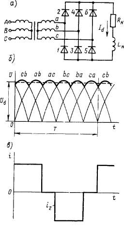
Rice. 1.13. Three-phase bridge rectifier
With single-phase rectification, voltage ripples at the load ^-load are very significant, and the frequency of the variable component is 2 times higher than the frequency of the alternating current (Fig. 1.12, b). With a three-phase bridge rectification, the circuit turns out to be six-cycle and the voltage ripple is small - less than 6% of the constant component (Fig. 1.13, b).
The current in the load circuit is usually smoother than the voltage, since the load circuit often contains inductance, which presents a large resistance for the AC component of the current and a small resistance for the DC component.
If we consider the current in the load /<* полностью сглаженным, то по обмоткам трансформатора проходит ток, имеющий вид прямоугольников (рис. 1.12,6 и 1.13, in), containing higher harmonics that increase the heating of the windings. In addition, when using zero-point rectification circuits, there is a constant current component in the windings (Fig. 1.12.6). Because of this, the effective value of the current increases sharply and measures must be taken against creating a permanent magnetization of the rod. To prevent this phenomenon, for example, in single-phase transformers, either armored construction (Fig. 1.14), or all the windings of the transformer are placed on each rod, dividing them in half.
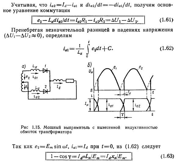
Great influence on the operation of the rectifier (Fig. 1.15, o) provides current switching - the process of transition from one valve to another.
Due to the presence of inductances in the current-carrying circuit and the inductance due to leakage fluxes of the transformer, the current from one valve passes to another not instantly, but over the switching period T k, which corresponds to the switching angle at(Fig. 1.15, b).
For simplicity, we assume that the current in the load ID perfectly smoothed. Then the sum of the currents through the first and second valves i a \ and iai during the switching process is unchanged:
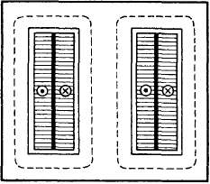
Rice. 1.14. Schematic drawing of an armored transformer
At the start of switching, when the EMF value passes through zero and changes sign, the transformer winding becomes short-circuited and the equation can be written for its circuit
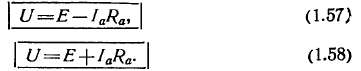
During switching, the voltage at the load SLg \u003d 0.5 (e 2a + + e 2 b) and in a single-phase rectifier is zero (Fig. 1.15, b). Therefore, due to switching, the rectified voltage decreases and its ripple increases. Since the switching angle is greater, the greater the load current I d and inductive reactance x a, to improve the quality of the rectifier, it is desirable that the machine that feeds it has a small inductive resistance. In a transformer x a equal to the inductive reactance due to leakage fluxes, and is determined from the experience of a short circuit In a synchronous generator
where Ha" and xq"- supertransient inductances along the longitudinal and transverse axes, respectively, taking into account the presence of current in the damper winding.
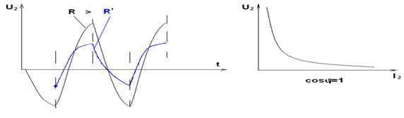
Thus, synchronous generators designed to operate on a rectifier must be designed to operate with non-sinusoidal current and have a damper winding.
The power factor of a generator powered by an unregulated rectifier is
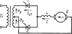
Rice. 1.16. Scheme of a single-phase inverter
where v "0.9 - distortion factor; > f «0.5 y is the angle of the current shift relative to the first harmonic of the voltage.
DC to AC conversion is produced using inverters that use controlled valves: transistors, thyristors, etc.
The diagram of a single-phase inverter is shown in fig. 1.16. The inverter valves are turned on alternately every half-cycle so that the direction of the current in the secondary winding of the transformer is opposite to the direction of the EMF in this winding, i.e., so that the energy is transferred from the DC source to the AC network.
Inverters have a relatively complex automatic control system, which increases their cost and reduces reliability compared to uncontrolled rectifiers.
In addition, the inverter may have a mode through combustion, when the current in the winding is in phase with its EMF. This mode is possible either in case of a malfunction in the control system, or if the switching angle is too large. With through burning, the current usually increases to an unacceptable value and usually semiconductor valves fail. A large number of elements in the control system and the possibility of emergency through-burning make the reliability of inverters much lower than that of uncontrolled rectifiers: the time between failures is reduced by 50...100 times.
The idea of power supply from inverters of asynchronous and synchronous motors is promising. By changing the switching frequency of the valves, it is possible to change the frequency of the voltage at the motor stator terminals and thereby economically (without resistance) regulate the angular velocity. This method of speed control is called frequency. However, the low reliability of systems with frequency inverters hinders their wide application.
At present, frequency regulation of speed is used only in special conditions where DC motors immersed in liquid cannot work: motors of ships, oil pipelines, motors of ball mills, etc.
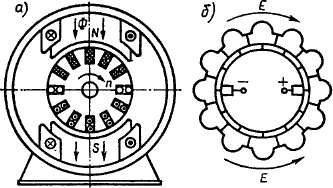
Rice. 1.17. DC machine device
There are experimental samples with frequency regulation in crane and traction electrical equipment.
The DC machine has a kind of converter-collector, which in the generator mode is a rectifier, and in the motor mode it is a frequency converter.
The design of a DC machine is similar to the design of an inverted synchronous machine, in which the armature winding is located on the rotor, and the magnetic poles are fixed. When the armature (rotor) rotates, an EMF is induced in the winding conductors, directed as shown in the cross section of Fig. 1.17, a.
In conductors located on one side of the line of symmetry separating the poles, the EMF is always directed in one direction, regardless of the angular velocity. During rotation, some conductors go under the other pole, other conductors come in their place, and in space, under the pole of one polarity, the picture is almost motionless, only some conductors are replaced by others. Therefore, it is possible to obtain a practically unchanged EMF from this part of the winding.
Constant EMF is obtained by means of a sliding contact between the winding and the external electrical circuit.
Conductors are connected in turns with a pitch wsht, as in AC machines, and then the turns are connected in series one after the other, a closed winding is formed.
In half of the winding (in a two-pole machine), an EMF of one sign is induced, and in the other - the opposite, as shown in the equivalent winding circuit (Fig. 1.17, b). Along the contour of the winding, the EMF in its parts are directed oppositely and are mutually balanced. As a result, when the generator is idling, i.e., in the absence of an external load, no current passes through the armature winding.
The external circuit is connected to the armature through brushes mounted on the geometric neutral.
To improve contact, the brushes are made in the form of rectangular graphite bars, and they slide along the surface of the collector, which is assembled from copper plates isolated from each other.
In large machines, the beginning and end of each turn are attached to the collector plates; in small plate machines
less than turns, and therefore a part of the winding of several turns is soldered between the two plates - a section.
Under load, a current flows through the armature conductors, the direction of which is determined by the direction of the EMF.
Due to the fact that the load current is constant, in the turns of the armature winding the current has a shape close to rectangular (Fig. 1.18, a).
When a coil passes from one parallel branch to another, it is short-circuited by a brush for a time called switching period(Fig. 1.18, b)
T K \u003d bJv KOn ,(1.66)
where b u- brush width; and K ol is the linear speed of a point located on the surface of the collector.
In the simplest case, when the brush is narrower than the collector plate, for the section closed by the brush (Fig. 1.18.0),
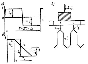
Rice. 1.18. Switching current diagrams
where iiRi=AUi and i 2 R2=AU 2- voltage drop in the brush contact, respectively, with the first and second collector plates; Rc- active resistance of the section; L pe3 - resulting inductance of the section; e to- EMF from an external field. Neglecting iR c because of the smallness R c , we get
The resulting basic commutation equation(1.68) coincides with the switching equation in the rectifier(1.61). The solution of this equation is easy to obtain by assuming that
So that when the first plate leaves the brush, there is no break in the current, at the time t = T K the current through the first plate must be equal to zero:
This condition for sparkless switching is reduced to the fact that in all modes the switching angle at was unchanged:
y=*T K =2vJ>JD a v Koll =2b"jD a , (1.71)
where D a- anchor diameter; v a - linear speed of a point located on the anchor surface; b "u \u003d bshO a / O KO l- the width of the brush, reduced to the diameter of the armature.
To fulfill this condition, the EMF in the EMF switching zone e to is created by special additional poles, the winding of which is connected in series to the armature circuit, and their magnetic circuit is made unsaturated.
The switching process in rectifiers, inverters and DC machines is similar. In both cases, the process of changing the current during the switching period is determined by the value and shape of the EMF in the short-circuited circuit. Therefore, it is impossible to liken the collector to a mechanical rectifier, as is sometimes done.
The presence of a collector also introduces its own characteristics: the design of the machine becomes more complicated and operation becomes more expensive. However, these shortcomings of electric machines are redeemed by their main advantage: in the motor mode, random switching disturbances usually lead to a slight burn of the collector and brushes, and not to emergency operation. overturning, like inverters.
As a result, the reliability of the DC collector machine is much higher than the reliability of the "asynchronous motor-frequency converter" system, its efficiency is 3 ... 5% higher, the machine is much cheaper, has smaller dimensions and weight.
These advantages make it necessary to give preference to a DC machine, limiting the use of an asynchronous motor with frequency control to the narrow framework of specific devices (motors operating in a liquid, etc.).