The backlight of the matrix on the laptop does not work. Repair of LCD, LCD, LED TVs with a faulty LCD matrix backlight
Hi all. Today we are repairing a Samsung UE32F5000AK with the fault “no LED backlight matrix". I very rarely repair such TVs, since I have neither the equipment nor the amenities to repair such equipment. But nevertheless, this time I decided to try, and the owner of the TV really insisted.
So, let's begin.
Preliminary diagnostics of the TV
When you turn on the TV, there is sound, but no picture. The TV responds to the remote control and buttons. If you look closely, you can see that there is an image on the matrix, but there is no LED backlight. From this we can conclude that the backlight control driver itself is faulty, or some line of LEDs has burned out.
Disassembling the TV
Having determined the possible malfunction, I began disassembling it. Having placed the TV matrix on the table, the first thing I did was remove the stand, which is held on by three bolts. Next, I unscrewed the remaining 10 bolts around the perimeter, after which I was able to remove the back cover.
When removing back cover, you need to keep an eye on the cable from the joystick, which needs to be disconnected, after which the cover can be set aside.

The TV consists of three boards, namely the power supply, on the board of which the backlight driver is assembled, on the left is the main board, and on the bottom is the t-con matrix control board.
Troubleshooting
IN LED TVs all LEDs are connected in series. This means that if any of the LEDs breaks, the entire LED backlight will stop working. As I said earlier, there are two main reasons for backlight failure: LEDdriver or LEDs.
If the driver is faulty, then for the most part, no voltage is supplied to the LEDs. If the line of LEDs is faulty, then a voltage of about 200 volts will flow to the power supply terminal, sometimes it can pulsate from 150 to 200. This indicates that the driver is trying to illuminate the backlight, but there is no load as LEDs, and the driver produces the maximum voltage. This process I personally understand it this way.
Having removed the power supply board, I determined that power to the LEDs is supplied through the D9101C to the capacitor, after which I decided to measure the voltage on it. Having connected the multimeter, it turned out that the voltage on it was in the range of 190-210V.

This means that the driver is running idle, and the problem is in the LED line itself. For me it wasn't very good good news, since I am very reluctant to take on disassembling matrices due to inexperience and lack of conditions for repairs.
Disassembling the LED LCD matrix
With the motto “do no harm,” I began disassembling the matrix. Having prepared the second table on which I will assemble the matrix, the first thing I did was disconnect the cable from the LCD panel to the T-con board. Having examined the structure of the TV in more detail, I saw that the matrix itself is supported by 2 frames, which are secured with latches. I removed the first frame from the beginning. To do this, I placed the TV on the back wall, and gradually, starting from the top, I began to unlatch the latches. Special attention turned to the bottom of the matrix so as not to damage the cables. The top frame came off very easily.
 Next, holding the matrix, I placed the TV on the front, with the cables down.
Carefully removed the matrix boards (decoders) from the grooves so that they began to hang freely.


Matrix decoders removed from latches
I will say right away that this is such a painstaking process that my nerves were on edge. Having released the decoders from the latches, he took the TV by the second frame and carefully lifted it. The matrix remained lying on the table.

Removed matrix

Having removed the matrix to another table, he continued disassembling. Clicking the second frame, I removed the scattering film and got to the LEDs.

Under the LEDs there is a white reflector, which is held on by 4 locking clips.

After removing them, I was able to remove the reflector.
The structure of LED TV backlighting.
As you can see from the picture, the TV matrix consists of five LED lines of nine LEDs each. If we take into account that each LED is powered by approximately 3 volts, then we have that one line of LEDs uses about 27 volts (3 * 9 = 27). In order to check which LED has burned out, we first find in which line the LED broke. To do this, we alternately connect 27V power to the line of 9 LEDs, and whichever line doesn’t light up is the one that breaks. Next, we connect 3V power to each LED one by one, and look for which LED is not lit.
In my case, it turned out to be very easy to identify a burnt-out LED, since it got very hot, as a result of which the diffusing lens on it changed color and got a little straighter.
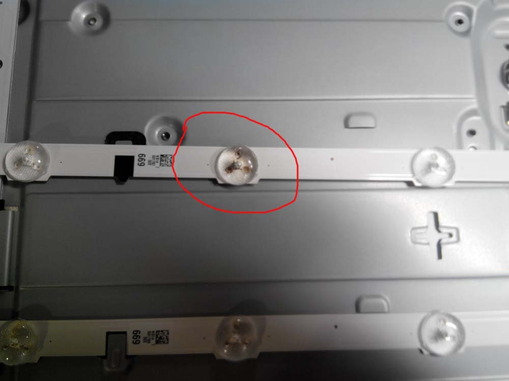
The temperature was such that the textolite with reverse side also burned out.

Having pulled out the lens, the LED fell out. For this I used a soldering gun. I applied flux on top of the LED and heated the board from below until it was unsoldered. So I decided to solder the new one too.

Finding a new LED is another task. After going through the radio market several times, I found similar LEDs in one of the stores, albeit already soldered. The man unsoldered them from the TV, on which the matrix was broken.
I also soldered the LED using a soldering gun. Having tinned the tracks, I placed the LED on it with the required polarity, and slowly heated the PCB from below until the LED was soldered. It was not sealed very nicely, because White paint got off, but securely.


By applying 27V power to the line, it lit up beautifully. Having glued the diverging lens, I folded the matrix in the reverse order. It should be noted that the repaired LED is slightly different in color, but in operating mode this is not noticeable at all.
Having completed the assembly, the TV started working.

After running for 8 hours, I gave the TV to the owner. It is worth noting that such a repair was the first time for me, and I am very pleased with its result. Perhaps I did some things wrong, please indicate them in your comments.
Suitable LEDs can be purchased on this page: LEDs 100 pieces lot
or batch of 50 pieces Here
Other LEDs for LED TVs:
LEDs 3535 2 watts 6 volts on LG (large area - cathode (-))
LEDs 6 volts on LG 2 watts size 3535 (large area - anode (+))
LEDs 6 volts on LG 1 W size 7030
LEDs 3 volts on LG 0.5 W size 7020
LEDs 3 volts on LG size 3528 (large area - anode (+))
LEDs 3 volts on Samsung 1 W size 3537
3 volt LEDs for Samsung size 7032
LEDs 3 volts on Samsung 0.5 W size 5630
Any other LEDs can be found Here.
A fairly common malfunction is that there is no backlight on the matrix. How this is expressed: the laptop turns on, works, the image on the matrix is very faintly visible, visible in reflected light. Let's look at this problem using the example of LED-backlit matrices. We need to localize the fault and fix it.
To turn on and operate the backlight, 3 conditions must be met:
- Availability of power on the driver, VLED or LED backlight power
- Presence of LED_EN or LED backlight ON/OFF signal
- Presence of PWM signal or DIMM PWM for Luminance control
The names of the signals may differ in different laptop circuits and matrix datasheets, but the essence is the same. The LED backlight driver is located on the matrix itself (the exception is Apple laptops, where the LED driver is located on the laptop's motherboard). All these signals come to the matrix from the laptop’s motherboard, but since opening the matrix cover is faster than disassembling the laptop, we will look for these signals on the matrix. For example, let's take a laptop with a standard 15.6 40pin matrix, the diagonal is not important, the principle is the same everywhere.
Let's disassemble the matrix cover... block diagram of the matrix to attract attention:

Let's look at the pinout of the LVDS connector on the matrix. We are interested in pins 35 to 40:
LED Power Supply (7V-20V) VLED - 40
LED Power Supply (7V-20V) VLED - 39
LED Power Supply (7V-20V) VLED - 38
No Connection (Reserved) NC - 37
Backlight On/Off Control BL_On - 36
PWM for Luminance control BLIM - 35
38,39,40 - This is the power supply for the LED driver, 36 - turn on the backlight, 35 - brightness (DIMM). It is convenient to carry out measurements directly on the matrix; as a rule, these signals have control points.

We are interested in the right side of the board. The black chip on the right is the LED driver.

Here in this photo you can see the VBL control point. This is the power supply for the backlight. There should be +19 volts. There is fuse F5 nearby, it wouldn't hurt to ring it. As a rule, if it is broken, then the problem is further in the driver. Do not try to replace the fuse with a bug! .
Have you checked the power supply at the VBL test point? There is no power - we disassemble the laptop and look at the motherboard diagram where it comes from.
Is there food? Then the next photo:

We are interested in 2 points: BL_EN and PWM. The first one should be +3.3 volts, the second one should be from 1.8 to 3 volts, depending on the set brightness. These signals come from the laptop motherboard, if there is no signal, then open the laptop circuit and study where they come from and call this circuit. There are signals and power, but there is no backlight - we measure the voltage at the test points next to the connector on the CON10 LEDs, there is nothing? This means it's time to change the LED IC7 driver.
There are a great many types of matrices, some may not have easily accessible control points, so for diagnostics I use a broken matrix on which all control points are visible and labeled. This makes life a lot easier.
Problems and solutions:
- There is no backlight power at the VBL point: there may be a problem in the cable, in the key (transistor) on the motherboard.
- One of the BL_EN and PWM signals is missing: there may be a problem with the cable or the motherboard.
- Both BL_EN and PWM signals are missing: a loop is also possible, but the symptom is alarming, there is a high probability that the problem is in the motherboard. Different laptop platforms generate these signals differently. General recommendations it can not be. Reading the laptop diagram. In some laptops, such a malfunction indicates a faulty north bridge.
We looked at standard LED backlighting with analogue PWM control; this principle is used in the vast majority of modern laptops. But in some laptops the PMW signal can be digital, for example in matrices for DELL.
This article is not a guide to action; remember that when disassembling a laptop, you act at your own peril and risk. The article was written to understand the general principles of laptop operation.
If you need to repair your laptop, fix the backlight on your laptop, or other problems with your laptop, contact the professionals!
Read 14624 once
The laptop display does not work or the image on the display is barely visible. We find out the cause of the malfunction. How to repair the display yourself. Replacing the matrix backlight lamp in a laptop, replacing the backlight module (inverter) of a laptop.
Such a malfunction as the lack of backlighting of the laptop matrix, blinking (jittering) of the backlight, reddish backlight of the laptop display, etc., occur quite often and there can be several reasons for their occurrence. Here are the most likely ones:
- The matrix inverter is faulty.
- The matrix backlight lamp has failed.
- The laptop lid closing sensor is broken (stuck in the pressed position).
- The laptop's standby power chip is faulty or partially damaged.
Below are photographs of disassembling the laptop display and methods for identifying this malfunction. The article uses materials from the “Computer Doctor” website www.pc-doc.spb.ru

We remove the rubber plugs to gain access to the mounting screws of the matrix frame.


After all the screws are removed, carefully peel off the laptop display.


Disconnect the backlight wires from the inverter.

To check the operation of the inverter, we connect a known-good matrix backlight lamp to it. If it lights up when you turn on the laptop, then the inverter is working.

We continue to dismantle the matrix from the display frame. Unscrew all fastening screws.


Disconnect the information cable of the matrix.


After removing the matrix, we continue to disassemble it in order to get to the backlight.


Remove the adhesive tape around the perimeter of the matrix where it is present.


Remove the remaining screws from the end of the matrix.


Very carefully remove the frame and peel off the matrix in the place where the backlight is located.

We remove the backlight lamp along with the metal reflector.

This photo shows that the light bulb not only burned out, but also cracked.

Now we replace the faulty backlight lamp with a new one and assemble the matrix in the reverse order. Attention! When dismantling and assembling the matrix, you need to be extremely careful so that the illumination of the matrix does not change. Sloppy or incorrect assembly may result in stains on the matrix. You also need to ensure that no dust or dust gets between the layers of the matrix. foreign objects, which will result in their projection on the screen after assembly. Good luck to you in this delicate and rather painstaking work!
Self-repair of laptop screen backlight inverter
A Samsung R505 laptop is being repaired with the following “diagnosis”: the screen does not work. When turned on, the indicators light up, the hard drive and fan start up, and the sounds of the hard drive heads moving are heard. This is a sign that there are no faults in the main part.
The screen is dark, but if you shine a flashlight at a certain angle, the image begins to be viewed. This indicates that the display backlight is faulty.
As you already know, the backlight itself often fails and just needs to be replaced. But first you need to make sure that this is the case. The backlight also has a so-called “inverter” - a small board that converts a low voltage of about 14 volts to the high voltage necessary to power a cold cathode lamp.
So, we disassemble the display by unscrewing the screws and removing the front panel. We disconnect the lamp from the inverter and connect a new one instead - the lamp does not light. Supply voltages are supplied to the inverter board, and there are also control signals (connector 1). We conclude that the inverter is faulty.
We check the lamp by connecting it to an external, working inverter - the lamp does not light. We make an assumption that the lamp is faulty.
We will repair it sequentially.
The inverter is designed very simply: a controller chip (3) generates a frequency and monitors the lamp current. Two assemblies field effect transistors(4 and 5) “pump” the primary winding of the step-up transformer (6). That's the whole inverter. It would seem that the use of a special controller chip should protect the inverter from any malfunctions. But, as we see in practice, it does not protect.
Let's start checking the details. It turns out that the SMD fuse (2) has blown. It's disposable. We check the field workers' assemblies - one P-channel transistor is short-circuited. This happens when there is an overload: either short circuit in the primary winding of the step-up transformer, or a short circuit at the output (7).
Field workers' assemblies are used here AO4604. You can use IRF7319 or IRF7309 instead. Perhaps suitable: IRF7389, NDS8839, NDS8858, Si4539DY, Si4542. More details can be found in the datasheets so that the pinouts and parameters match. Unfortunately, there was absolutely nothing of this in stock. Therefore, it was decided to bend the leads of that part of the assembly that turned out to be faulty from the board, and solder the transistor with wires in a “surface-mounted” manner. The ancient but good SMD10P was chosen as the transistor - “with a reserve”. The SMD fuse has been replaced with a jumper.
After replacing the parts, the inverter successfully started up with the new lamp. They didn’t dare check with the old lamp - and they did the right thing. Since there was a suspicion that it was faulty, it was decided to remove it. To do this, unscrew metal plates on the sides of the display, after which the entire “Sandwich” of glass and films is removed from the metal frame. Attention! You should not allow the display elements to delaminate, as dust will immediately get there, which will be almost impossible to remove.
During the process of removing the lamp, it was discovered that one of the ends of its silicone insulator had turned black and had traces of soot. So the reason for the failure of the inverter was discovered. A spark occurred at one of the lamp terminals, either between the torn wire and the terminal, or between the terminal and the metal frame of the display. In any case, the wire from the lamp has already burned out. The increased current led to an overload of one of the transistors, and when it burned out, the fuse also blew. Tellingly, the sophisticated controller chip didn’t even notice the overload.

The wire was soldered to the lamp and insulated with heat shrink tubing. After assembling the display and connecting the inverter, a full image appeared on the screen, the brightness was adjusted within the required limits.
A run for several hours showed reliable operation of the inverter. The renovation is complete.
Without such backlighting, no LCD TV can operate normally, regardless of its brand. We will tell you how you can repair your TV's LED backlight at home using an Lg device as an example, and what you will need for this.
How can you tell if the backlight is broken? Let's assume that the problem with the LCD TV is as follows: it turns on from the remote control, but the screen does not light up (if your TV does not turn on even from the remote control, read about). When pointed at the display flashlight light(i.e. forced illumination is applied), then the image appears. Verdict - the ice driver or similar backlight does not work, perhaps due to the fact that the special lines with soldered LEDs have burned out. You need to disassemble the TV and visually inspect the parts to find a fault.
Attention! You can only open the case of an LCD TV if you have the skills to work with complex devices and some experience in otherwise It's better not to take risks.
Remove the back cover For any LG TV, this is not a difficult task, you just need to do everything carefully and without haste: disconnect the legs of the stand and unscrew the mount around the entire perimeter of the product. If the cover does not come off, it means there is a blocking bolt, you should not make any effort, you need to find it and unscrew it.
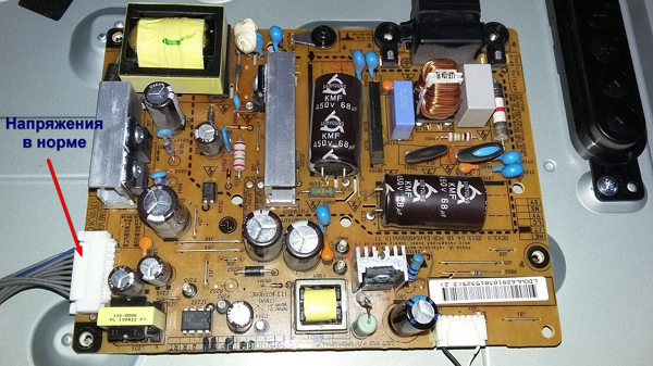
After removing the back cover, check the output voltage.
If it is normal, check it voltage ice backlight the screen itself. Its value is only 100V, which indicates a malfunction in the backlight of the LCD TV.
These TVs use a special LED set with lenses that are installed across the entire screen area to provide clear illumination. To get to them and repair the LG TV backlight, you must first remove the matrix.
Disassembling the product
The TV has three main boards - main, T-con and power supply, all of which are clearly visible in the photo.

Removing and disassembling the matrix do it yourself - the work is very painstaking, one careless movement, and you can buy a new TV, so without experience it is better not to undertake repairs. Experts highlight the following main points when disassembling the matrix:
- it is necessary to prepare a work area and two tables on which to lay matrices and scattering films;
- Before starting this work, you should thoroughly wash your hands so as not to accidentally leave traces of dirty fingers on the filters and the matrix itself - this can harm the quality of the image later;
- Special attention should be paid to decoders - one inaccurate movement can lead to a break in the cable.
Subsequent dismantling is carried out in several stages.

Troubleshooting
Now the actual repair of the LED backlight of the TV begins: to do this, you need to carefully unclip all the latches along the contour, remove the plastic frame and remove the diffusing films to expose the LEDs.


Different models of LG TVs will have their own set of LED backlights: for LG 32LN541U there are three rows of 7 LEDs, and for LG 32LB582V there are three rows of 6 LEDs.

In all TVs that use such backlighting, the LEDs are connected in series, so if one of them burns out, the entire system stops working.

If the LED driver is faulty, then no voltage is supplied to the entire system, and when one of the LEDs burns out, then the voltage flows, but all the efforts of the device to illuminate the system are in vain: even if you supply 200 volts, the circuit is open.
As we can see from the photograph, the backlight consists of 18 LEDs; during measurements, the voltage without load was 140 V, that is, each one accounted for 7.8 V. When we take into account the voltage drop on each strip and the total load, the conclusion will be as follows: this model uses 6V LEDs.

Finding a burnt-out LED is not easy: if there is no burnout at the mounting location, then you need to check each element separately.
Replacing LEDs Replacing the Lg TV backlight can be a bit of a hassle. Let's say that the test results revealed several faulty LEDs. It is quite difficult to buy a replacement bar - these parts are not supplied to service centers, you can order them on the manufacturer's website, but this is time-consuming and very expensive. So there is only one way - replace individual diodes
, although it will not be easy to find them on the radio market. Experts assure that you can buy already soldered ones, but in good working order; after a long search, these are exactly the ones we purchased. Users should be aware that all planks are glued using double sided tape , so you need to warm them up with a special soldering gun
so that the tape comes off. To do this, the bar is fixed in the holder and heated from below with a hairdryer, the tin is melted, and the faulty part is removed. Soldering should be done using exactly the same method to avoid damaging the LED.
Important! All lenses are secured with a compound at the factory, so when removing them you must act very carefully, and each one must then be installed in its original place so as not to disturb the original focusing.

The fact that the paint is a little damaged is not a problem. We solder the rest of the LEDs in the same way, and Glue the lenses with superglue. And this is a repaired view of the backlight panel assembled and ready for further use:

As we see in practice, there are many specific nuances in repairing the LED backlight of an LG TV matrix, and without knowing them, it is impossible to achieve a positive result.
Final works
When the LG TV system has been completely repaired, before final assembly, we connect the voltage to the strips and check the glow of all LEDs. If everything is fine, then we assemble the TV, performing all operations sequentially and with caution, as during dismantling.
After finishing, it is better not to turn the backlight brightness to maximum, but to limit it to 75% - in this mode, the LEDs operate in normal mode and, according to experts, will last much longer.
We install the TV in its original place, turn it on and enjoy the quality: if there are no extraneous spots of light or dark color anywhere on the screen, it means that the repair was carried out correctly, in compliance with all recommendations. And you can get the most out of your TV by learning how to properly