LED battery charge indicator circuit
Assessing the characteristics of a particular charger is difficult without understanding how an exemplary charge of a li-ion battery should actually proceed. Therefore, before moving directly to the diagrams, let's remember a little theory.
- How to properly charge lithium ion batteries
- what current
- how much time - What is a protection board (PCB module)?
- Charging schemes for li-ion batteries:
- LM317
- MAX1555 (MAX1551)
- LP2951
-MCP73831
- LTC4054 (STC4054)
- TP4056
- LTC1734
- TL431 + transistor
-MCP73812
- NCP1835 - Is it possible to charge a battery without a charge controller?
- How to charge a lithium battery?
What are lithium batteries?
Depending on what material the positive electrode of a lithium battery is made of, there are several varieties:
- with lithium cobaltate cathode;
- with a cathode based on lithiated iron phosphate;
- based on nickel-cobalt-aluminium;
- based on nickel-cobalt-manganese.
All of these batteries have their own characteristics, but since these nuances are not of fundamental importance for the general consumer, they will not be considered in this article.
Also, all li-ion batteries are produced in various sizes and form factors. They can be either cased (for example, the popular 18650 today) or laminated or prismatic (gel-polymer batteries). The latter are hermetically sealed bags made of a special film, which contain electrodes and electrode mass.
The most common sizes of li-ion batteries are shown in the table below (all of them have a nominal voltage of 3.7 volts):
| Designation | Standard size | Similar size |
|---|---|---|
| XXYY0, Where XX- indication of diameter in mm, YY- length value in mm, 0 - reflects the design in the form of a cylinder |
10180 | 2/5 AAA |
| 10220 | 1/2 AAA (Ø corresponds to AAA, but half the length) | |
| 10280 | ||
| 10430 | AAA | |
| 10440 | AAA | |
| 14250 | 1/2 AA | |
| 14270 | Ø AA, length CR2 | |
| 14430 | Ø 14 mm (same as AA), but shorter length | |
| 14500 | AA | |
| 14670 | ||
| 15266, 15270 | CR2 | |
| 16340 | CR123 | |
| 17500 | 150S/300S | |
| 17670 | 2xCR123 (or 168S/600S) | |
| 18350 | ||
| 18490 | ||
| 18500 | 2xCR123 (or 150A/300P) | |
| 18650 | 2xCR123 (or 168A/600P) | |
| 18700 | ||
| 22650 | ||
| 25500 | ||
| 26500 | WITH | |
| 26650 | ||
| 32650 | ||
| 33600 | D | |
| 42120 |
Internal electrochemical processes proceed in the same way and do not depend on the form factor and design of the battery, so everything said below applies equally to all lithium batteries.
How to properly charge lithium-ion batteries
Most the right way Lithium batteries are charged in two stages. This is the method Sony uses in all of its chargers. Despite a more complex charge controller, this ensures a more complete charge of li-ion batteries without reducing their service life.
Here we are talking about a two-stage charge profile for lithium batteries, abbreviated as CC/CV (constant current, constant voltage). There are also options with pulse and step currents, but they are not discussed in this article. You can read more about charging with pulsed current.
So, let's look at both stages of charging in more detail.
1. At the first stage A constant charging current must be ensured. The current value is 0.2-0.5C. For accelerated charging, it is allowed to increase the current to 0.5-1.0C (where C is the battery capacity).
For example, for a battery with a capacity of 3000 mAh, the nominal charge current at the first stage is 600-1500 mA, and the accelerated charge current can be in the range of 1.5-3A.
To ensure a constant charging current of a given value, the charger circuit must be able to increase the voltage at the battery terminals. In fact, at the first stage the charger works as a classic current stabilizer.
Important: If you plan to charge batteries with a built-in protection board (PCB), then when designing the charger circuit you need to make sure that the open circuit voltage of the circuit can never exceed 6-7 volts. IN otherwise The protection board may fail.
At the moment when the voltage on the battery rises to 4.2 volts, the battery will gain approximately 70-80% of its capacity (the specific capacity value will depend on the charging current: with accelerated charging it will be a little less, with a nominal charge - a little more). This moment marks the end of the first stage of charging and serves as a signal for the transition to the second (and final) stage.
2. Second charge stage- this is the battery charge constant voltage, but with a gradually decreasing (falling) current.
At this stage, the charger maintains a voltage of 4.15-4.25 volts on the battery and controls the current value.
As the capacity increases, the charging current will decrease. As soon as its value decreases to 0.05-0.01C, the charging process is considered complete.
An important nuance of the correct charger operation is its complete disconnection from the battery after charging is complete. This is due to the fact that for lithium batteries it is extremely undesirable for them to remain under high voltage for a long time, which is usually provided by the charger (i.e. 4.18-4.24 volts). This leads to accelerated degradation chemical composition battery and, as a result, a decrease in its capacity. Long-term stay means tens of hours or more.
During the second stage of charging, the battery manages to gain approximately 0.1-0.15 more of its capacity. The total battery charge thus reaches 90-95%, which is an excellent indicator.
We looked at two main stages of charging. However, coverage of the issue of charging lithium batteries would be incomplete if another charging stage were not mentioned - the so-called. precharge.
Preliminary charge stage (precharge)- this stage is used only for deeply discharged batteries (below 2.5 V) to bring them to normal operating mode.
At this stage the charge is ensured DC reduced value until the battery voltage reaches 2.8 V.
The preliminary stage is necessary to prevent swelling and depressurization (or even explosion with fire) of damaged batteries that have, for example, an internal short circuit between the electrodes. If a large charge current is immediately passed through such a battery, this will inevitably lead to its heating, and then it depends.
Another benefit of precharging is pre-warming the battery, which is important when charging at low temperatures environment(in an unheated room during the cold season).
Intelligent charging should be able to monitor the voltage on the battery during the preliminary charging stage and, if the voltage does not rise for a long time, draw a conclusion that the battery is faulty.
All stages of charging a lithium-ion battery (including the pre-charge stage) are schematically depicted in this graph: 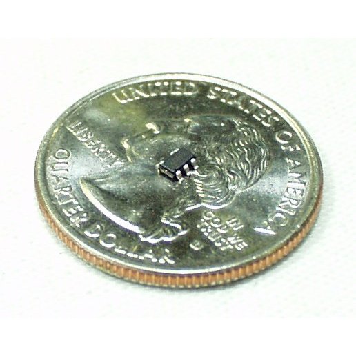
Exceeding the rated charging voltage by 0.15V can reduce the battery life by half. Lowering the charge voltage by 0.1 volt reduces the capacity of a charged battery by about 10%, but significantly extends its service life. The voltage of a fully charged battery after removing it from the charger is 4.1-4.15 volts.
Let me summarize the above and outline the main points:
1. What current should I use to charge a li-ion battery (for example, 18650 or any other)?
The current will depend on how quickly you would like to charge it and can range from 0.2C to 1C.
For example, for a battery size 18650 with a capacity of 3400 mAh, the minimum charge current is 680 mA, and the maximum is 3400 mA.
2. How long does it take to charge, for example, the same 18650 batteries?
The charging time directly depends on the charging current and is calculated using the formula:
T = C / I charge.
For example, the charging time of our 3400 mAh battery with a current of 1A will be about 3.5 hours.
3. How to properly charge a lithium polymer battery?
All lithium batteries charge the same way. It doesn't matter whether it is lithium polymer or lithium ion. For us, consumers, there is no difference.
What is a protection board?
The protection board (or PCB - power control board) is designed to protect against short circuit, overcharging and overdischarging of the lithium battery. As a rule, overheating protection is also built into the protection modules.
For safety reasons, the use of lithium batteries in household appliances, if they do not have a built-in protection board. That's why all cell phone batteries always have a PCB board. The battery output terminals are located directly on the board: 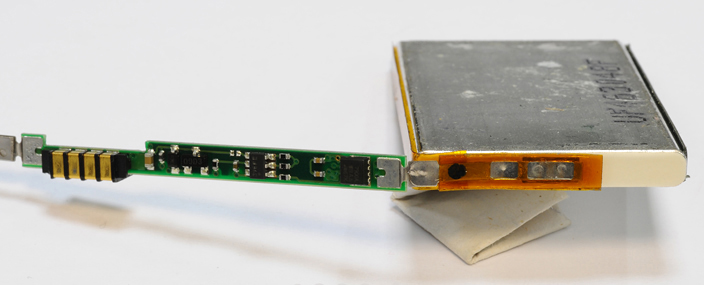
These boards use a six-legged charge controller on a specialized device (JW01, JW11, K091, G2J, G3J, S8210, S8261, NE57600 and other analogues). The task of this controller is to disconnect the battery from the load when the battery is completely discharged and disconnect the battery from charging when it reaches 4.25V.
Here, for example, is a diagram of the BP-6M battery protection board that was supplied with old Nokia phones: 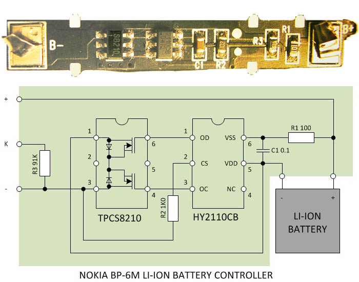
If we talk about 18650, they can be produced either with or without a protection board. The protection module is located near the negative terminal of the battery. 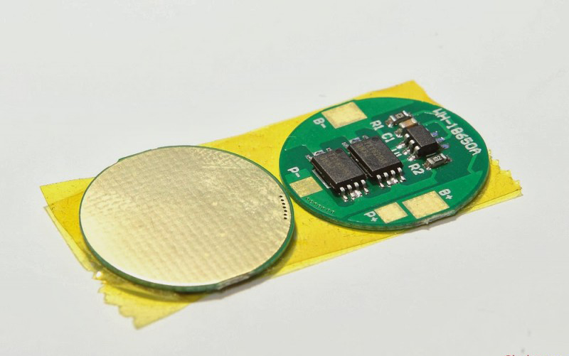
![]()
The board increases the length of the battery by 2-3 mm. 
Batteries without a PCB module are usually included in batteries that come with their own protection circuits.
Any battery with protection can easily turn into a battery without protection; you just need to gut it. 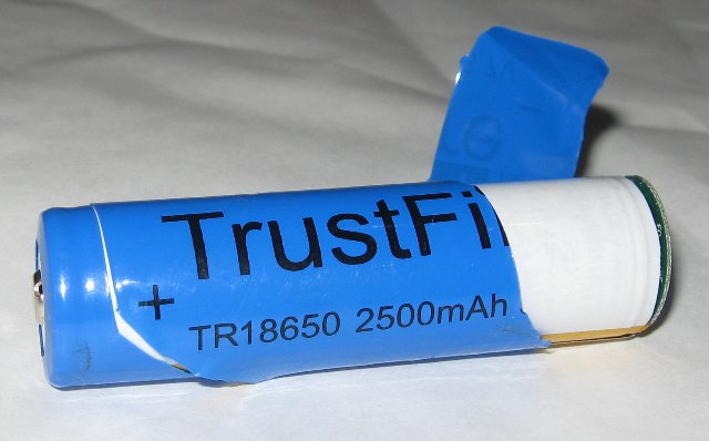
Today, the maximum capacity of the 18650 battery is 3400 mAh. Batteries with protection must have a corresponding designation on the case ("Protected"). 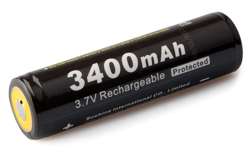
Do not confuse the PCB board with the PCM module (PCM - power charge module). If the former serve only the purpose of protecting the battery, then the latter are designed to control the charging process - they limit the charge current at a given level, control the temperature and, in general, ensure the entire process. The PCM board is what we call a charge controller.
I hope now there are no questions left, how to charge an 18650 battery or any other lithium battery? Then we move on to a small selection of ready-made circuit solutions for chargers (the same charge controllers).
Charging schemes for li-ion batteries
All circuits are suitable for charging any lithium battery; all that remains is to decide on the charging current and the element base.
LM317
Diagram of a simple charger based on the LM317 chip with a charge indicator: 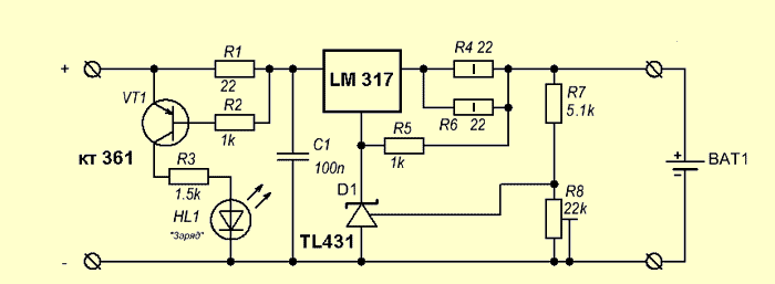
The circuit is the simplest, the whole setup comes down to setting the output voltage to 4.2 volts using trimming resistor R8 (without a connected battery!) and setting the charging current by selecting resistors R4, R6. The power of resistor R1 is at least 1 Watt.
As soon as the LED goes out, the charging process can be considered completed (the charging current will never decrease to zero). It is not recommended to keep the battery on this charge for a long time after it is fully charged.
The lm317 microcircuit is widely used in various voltage and current stabilizers (depending on the connection circuit). It is released in various options buildings: 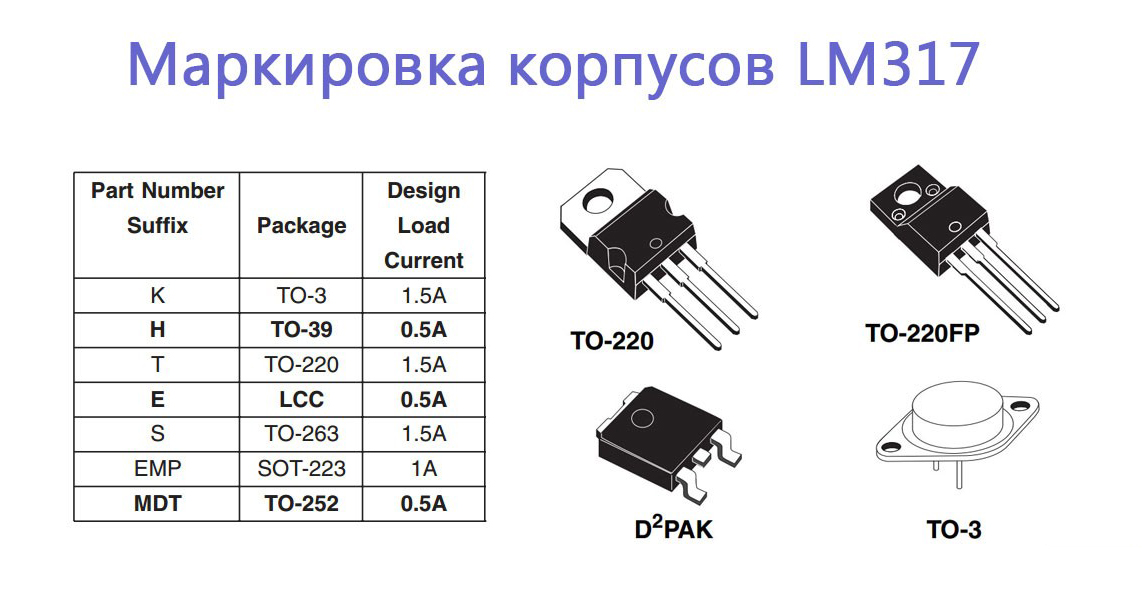
Pin assignment (pinout): 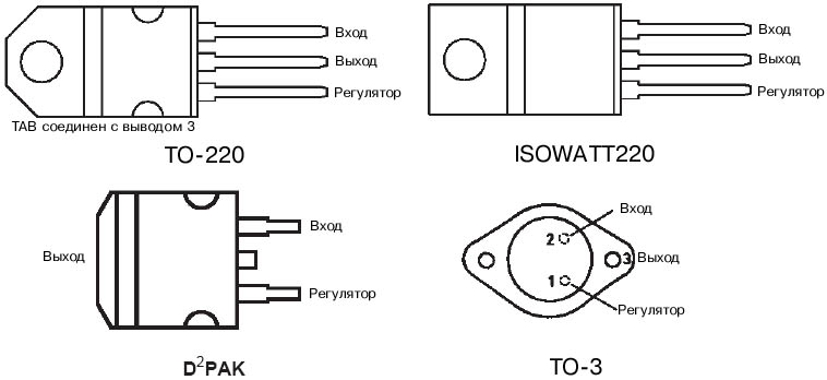
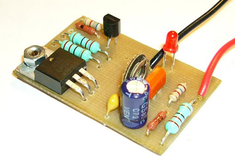
The printed circuit board and circuit assembly are shown below: 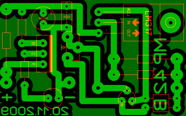
Analogues of the LM317 chip are: GL317, SG31, SG317, UC317T, ECG1900, LM31MDT, SP900, KR142EN12, KR1157EN1 (the last two are domestically produced). If you take the LM350, the charging current can be increased to 3A.
The old Soviet transistor KT361 can be replaced with a similar one pnp transistor(for example, KT3107, KT3108 or bourgeois 2N5086, 2SA733, BC308A). It can be removed altogether if the charge indicator is not needed.
Disadvantage of the circuit: the supply voltage must be in the range of 8-12V. This is due to the fact that for normal operation of the LM317 chip, the difference between the battery voltage and the supply voltage must be at least 4.25 Volts. Thus, it will not be possible to power it from the USB port.
MAX1555 or MAX1551
MAX1551/MAX1555 are specialized chargers for Li+ batteries, capable of operating from USB or from a separate power adapter (for example, a phone charger). The microcircuit does not require either external diodes or external transistors. Gorgeous little gadgets, only 5 outputs. Only they are too small and inconvenient to solder!
The only difference between these microcircuits is that MAX1555 produces a signal to indicate the charging process, and MAX1551 produces a signal that the power is on. Those. 1555 is still preferable in most cases.
A detailed description of these microcircuits from the manufacturer is.
The maximum input voltage from the DC adapter is 7 V, when powered by USB - 6 V. When the supply voltage drops to 3.52 V, the microcircuit turns off and charging stops.
The microcircuit itself detects at which input the supply voltage is present and connects to it. If the power is supplied via the USB bus, then maximum current The charge is limited to 100 mA - this allows you to plug the charger into the USB port of any computer without fear of burning the south bridge.
When powered by a separate power supply, the typical charging current is 280 mA.
The chips have built-in overheating protection. But even in this case, the circuit continues to operate, reducing the charge current by 17 mA for each degree above 110 ° C.
There is a pre-charge function (see above): as long as the battery voltage is below 3V, the microcircuit limits the charge current to 40 mA.
Typical connection diagram: 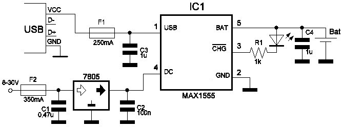
If there is a guarantee that the voltage at the output of your adapter cannot under any circumstances exceed 7 volts, then you can do without the 7805 stabilizer.
The USB charging option can be assembled, for example, on this one. 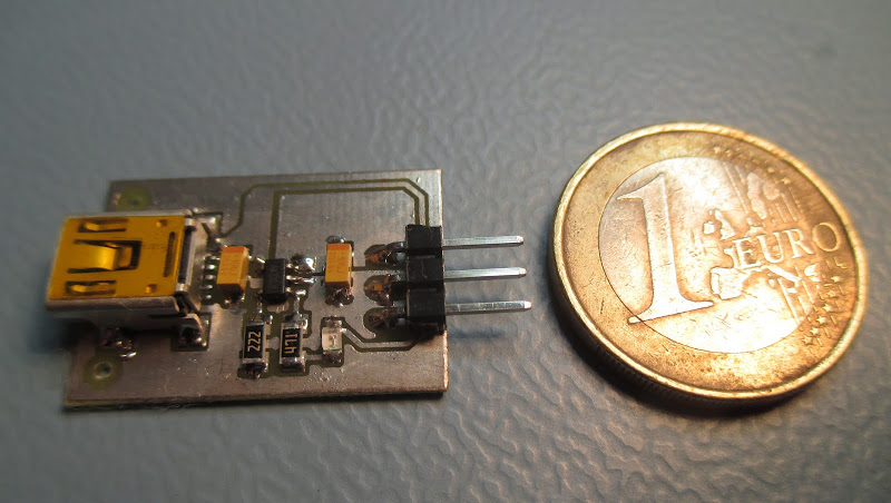
LP2951
The LP2951 stabilizer is manufactured by National Semiconductors (). It provides the implementation of a built-in current limiting function and allows you to generate a stable charge voltage level for a lithium-ion battery at the output of the circuit.
The charge voltage is 4.08 - 4.26 volts and is set by resistor R3 when the battery is disconnected. The voltage is kept very accurately.
The charge current is 150 - 300mA, this value is limited by the internal circuits of the LP2951 chip (depending on the manufacturer).
Use the diode with a small reverse current. For example, it can be any of the 1N400X series that you can purchase. The diode is used as a blocking diode to prevent reverse current from the battery into the LP2951 chip when the input voltage is turned off. 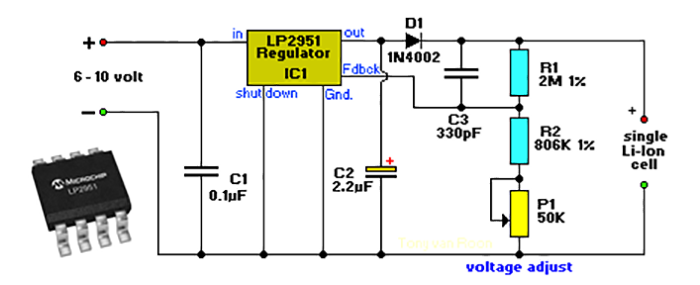
This charger produces a fairly low charging current, so any 18650 battery can charge overnight.
MCP73831
The chip allows you to create the right chargers, and it’s also cheaper than the much-hyped MAX1555. 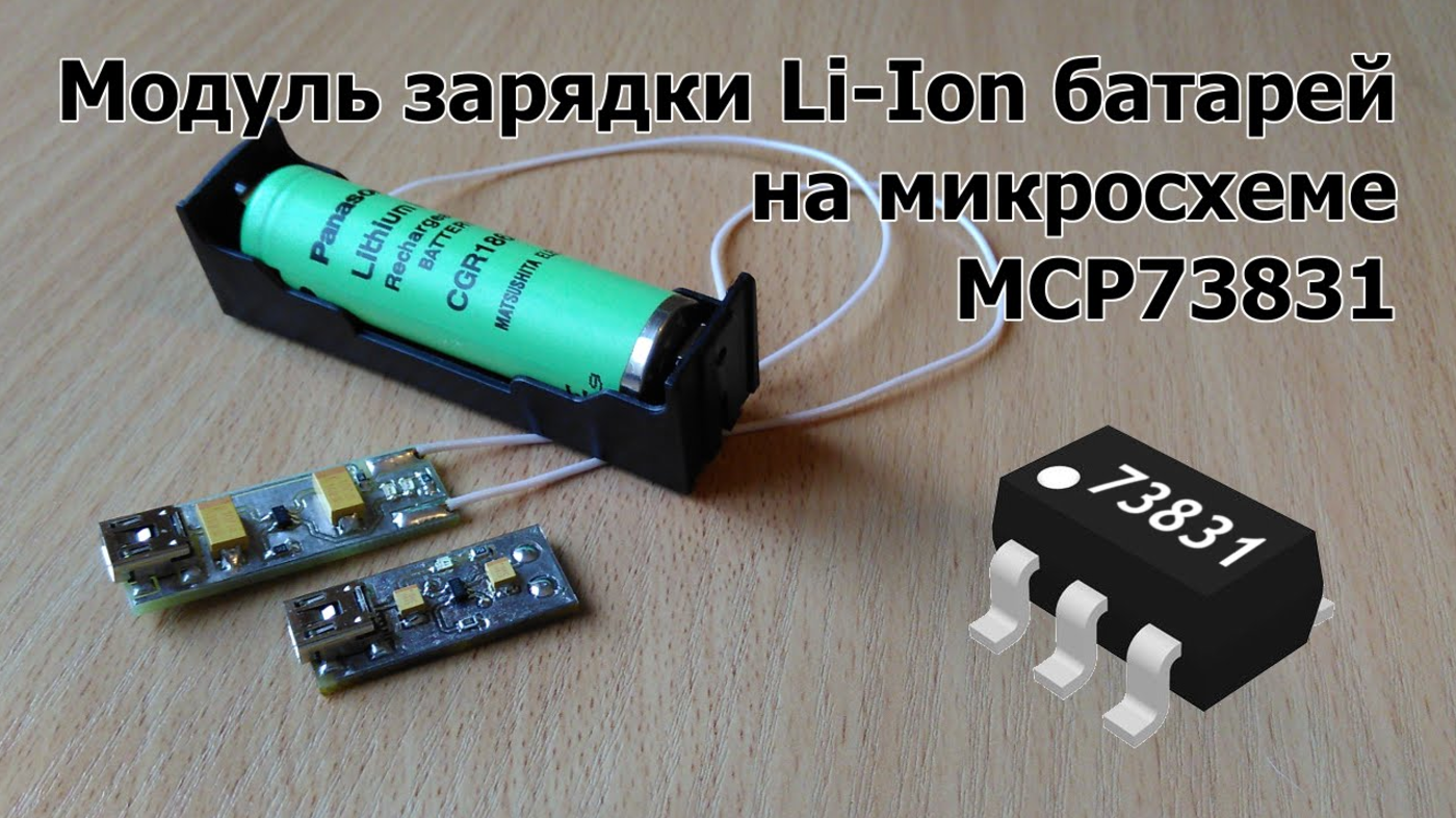
A typical connection diagram is taken from: 
An important advantage of the circuit is the absence of low-resistance powerful resistors that limit the charge current. Here the current is set by a resistor connected to the 5th pin of the microcircuit. Its resistance should be in the range of 2-10 kOhm.
The assembled charger looks like this: 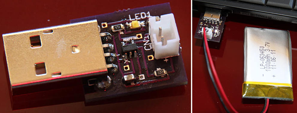
The microcircuit heats up quite well during operation, but this does not seem to bother it. It fulfills its function.
Here is another PCB option with smd led and micro USB connector: 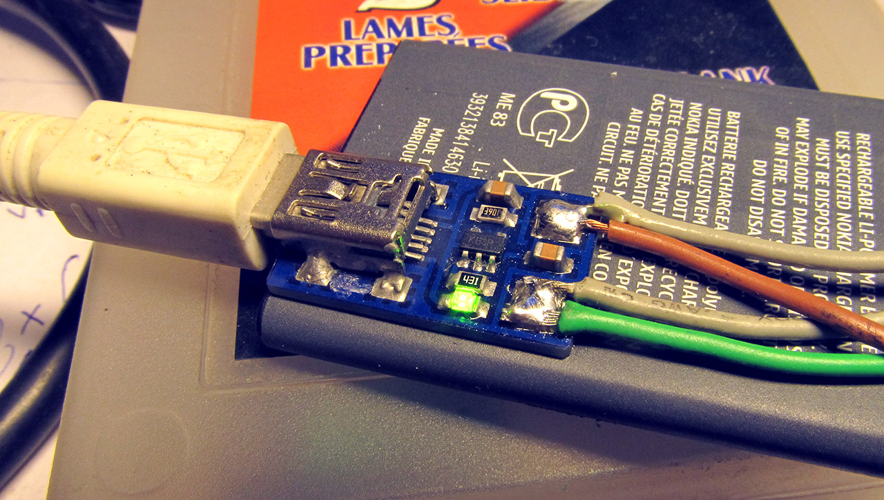
Can I charge a lithium-ion battery without a controller?
Yes, you can. However, this will require close control of the charging current and voltage.
In general, it will not be possible to charge a battery, for example, our 18650, without a charger. You still need to somehow limit the maximum charge current, so at least the most primitive memory will still be required.
The simplest thing Charger for any lithium battery, this is a resistor connected in series with the battery: 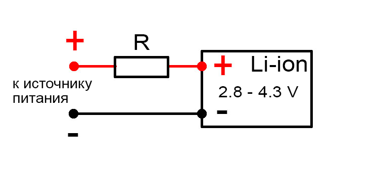
The resistance and power dissipation of the resistor depend on the voltage of the power source that will be used for charging.
As an example, let's calculate a resistor for a 5 Volt power supply. We will charge an 18650 battery with a capacity of 2400 mAh.
So, at the very beginning of charging, the voltage drop across the resistor will be:
U r = 5 - 2.8 = 2.2 Volts
Let's say our 5V power supply is rated for a maximum current of 1A. The circuit will consume the highest current at the very beginning of the charge, when the voltage on the battery is minimal and amounts to 2.7-2.8 Volts.
Attention: these calculations do not take into account the possibility that the battery may be very deeply discharged and the voltage on it may be much lower, even to zero.
Thus, the resistor resistance required to limit the current at the very beginning of the charge at 1 Ampere should be:
R = U / I = 2.2 / 1 = 2.2 Ohm
Resistor power dissipation:
P r = I 2 R = 1*1*2.2 = 2.2 W
At the very end of the battery charge, when the voltage on it approaches 4.2 V, the charge current will be:
I charge = (U ip - 4.2) / R = (5 - 4.2) / 2.2 = 0.3 A
That is, as we see, all values do not go beyond the permissible limits for a given battery: the initial current does not exceed the maximum permissible charging current for a given battery (2.4 A), and the final current exceeds the current at which the battery no longer gains capacity ( 0.24 A).
The main disadvantage of such charging is the need to constantly monitor the voltage on the battery. And manually turn off the charge as soon as the voltage reaches 4.2 Volts. The fact is that lithium batteries tolerate even short-term overvoltage very poorly - the electrode masses begin to quickly degrade, which inevitably leads to loss of capacity. At the same time, all the prerequisites for overheating and depressurization are created.
If your battery has a built-in protection board, which was discussed just above, then everything is greatly simplified. When a certain voltage is reached on the battery, the board itself will disconnect it from the charger.
The protection built into the battery will not allow it to be overcharged under any circumstances. All you have to do is control the charge current so that it does not exceed the permissible values for a given battery (protection boards cannot limit the charge current, unfortunately).
How to charge lithium batteries?
And if we are talking about a disposable battery that is not intended for recharging, then the correct (and only correct) answer to this question is NO.
The fact is that any lithium battery (for example, the common CR2032 in the form of a flat tablet) is characterized by the presence of an internal passivating layer that covers the lithium anode. This layer prevents chemical reaction anode with electrolyte. And the supply of external current destroys the above protective layer, leading to damage to the battery.
By the way, if we talk about the non-rechargeable CR2032 battery, then the LIR2032, which is very similar to it, is already a full-fledged battery. It can and should be charged. Only its voltage is not 3, but 3.6V.
How to charge lithium batteries (be it a phone battery, 18650 or any other li-ion battery) was discussed at the beginning of the article.
The review will include a study of the few characteristics of this module, a slight modification to adjust the indication thresholds, and installation of a power bank with three lithium batteries (3S connection circuit) into the case. There was already a similar board for one lithium battery, but there the author boasted more about his “collective farm” and did not study the board itself. This review will contain a complete circuit diagram and modification of the board.
While ordering another electronic item from DX, I accidentally noticed this module and remembered that I had an ancient one lying around Power Bank(hereinafter I will call it PB to avoid disputes about the correct spelling) which does not even have an indication of the battery charge level. After some hesitation, I added it to my cart. I would not buy such a board separately. Laziness goes to the post office to buy hundred-ruble bags and my conscience does not allow me to bother sellers with such a trifle. By the way, I ask you in advance not to reveal to me the truth that in other stores these boards are several times cheaper. I took it here solely because of convenience (added to a large order). The difference of 100 rubles is insignificant for me.
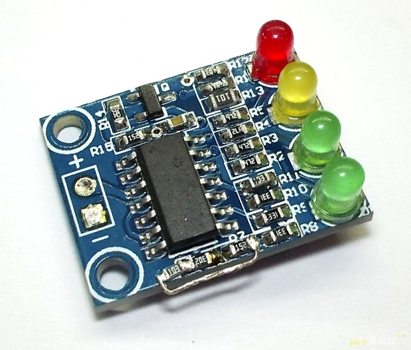
The board arrived in a small antistatic bag. 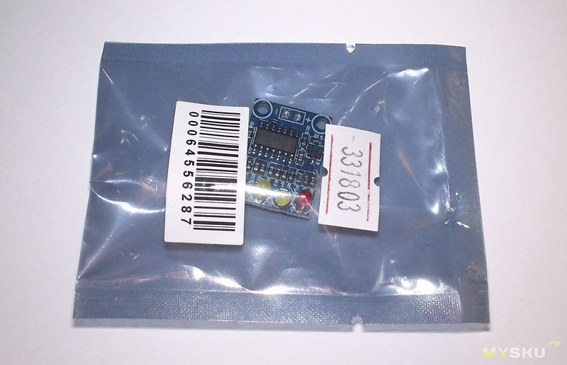
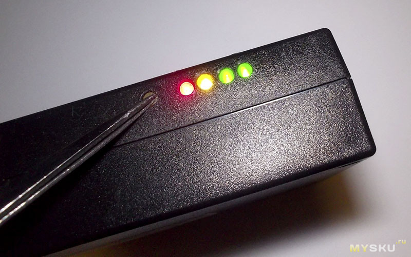
All elements are located on one side. Two contacts for connecting the battery for soldering. Indication by four LEDs, each of which turns on at a certain voltage value on the battery. The board is powered by the same voltage that it measures. The edges are not processed (textolite fibers were sticking out). The installation of the elements is neat, only the LEDs are sealed crookedly and filled with unwashed flux. I give the machine a five, the installer a two. 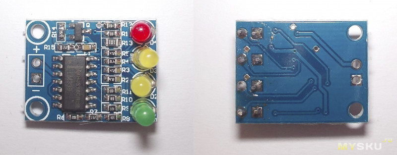
The board seems completely microscopic. 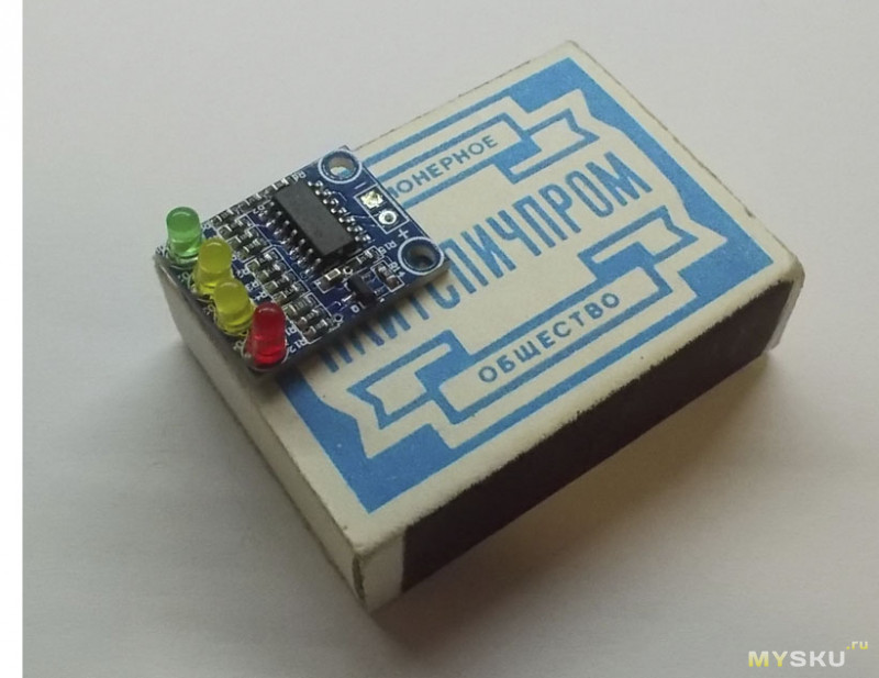
I started with the main thing - I measured the response thresholds of the LEDs. 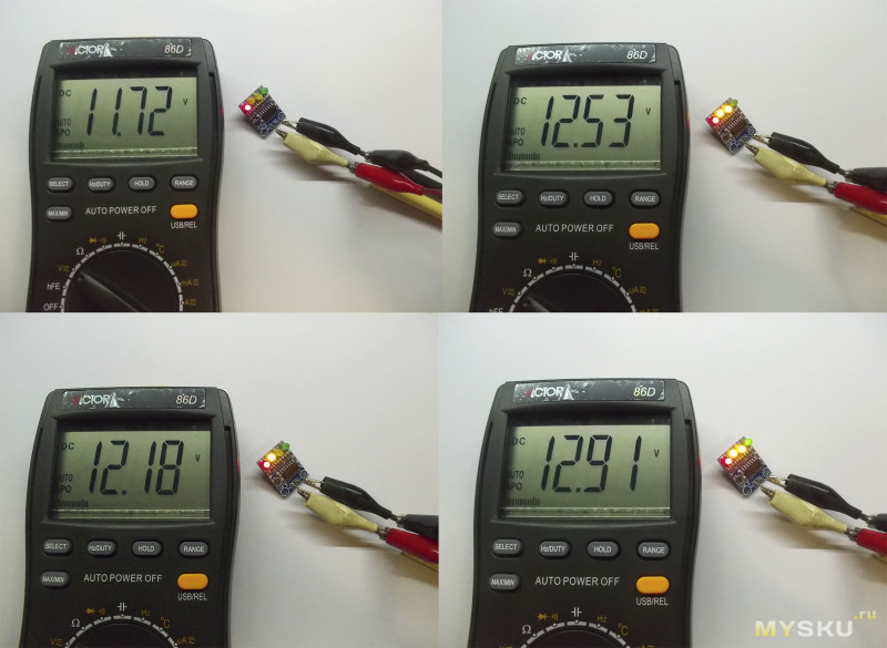
In a small voltage range (tens of millivolts), the LED blinks or lights dimly. After several repetitions I got the following threshold values:
- red LED: 11.7 V;
- 1st yellow LED: 12.1 V;
- 2nd yellow LED: 12.5 V;
- green LED: 12.9 V.
Consumption from 26 mA (11 V, LEDs are not lit) to 59 mA (14 V, all LEDs are lit).
It immediately became clear that the board was made for a lead-acid battery. It's a shame, I have lithium. At a voltage of 3.9 V per element (slightly discharged), even the red LED will go out. Of course, I didn’t expect the bells and whistles of the indicator. Was hoping for something like . No worries, I'll improve it. Before that I redrew the diagram. 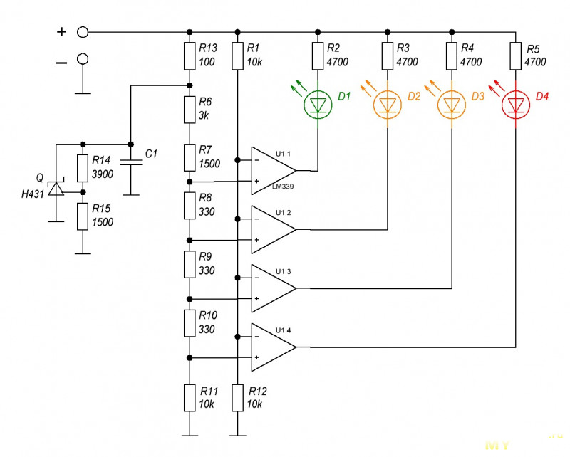
Nothing revolutionary. Parallel stabilizer (stabilizer with parallel connection of a control element, in in this case R14, R15) using a resistive divider R6...R11 generates a series of reference voltages, which are supplied to the non-inverting inputs of four comparators (one microcircuit, open-collector transistor output). The inverting inputs are supplied with supply voltage after the divider R1, R12. When the voltage at the inverting input exceeds the voltage at the non-inverting input, the output transistor opens and turns on the corresponding LED. There are many varieties of such a scheme (,), but the principle of operation is the same for all. You can read in more detail. Sometimes another LED is added that operates continuously, which increases the number of indication levels to five.
Modification for lithium
The modification was reduced to changing the parameters of the divider R6...R11, taking into account the typical voltages of lithium batteries (3...4.2 V, three in series). The required indication range is 9…12.6 V. It turned out that I had very few resistors of this standard size, I was too lazy to take out a hairdryer and solder them out of the radio junk, so after a few experiments I managed to get by with adding two 10 kOhm resistors. While still working, I decided to align the LEDs. As a result, three out of four stopped working. After a little shock, I realized that the board is not very good with the metallization of the holes, and the soldering is only on one side. I tinned it again, sparing no rosin and solder. All LEDs worked except one yellow one. I applied a couple of volts directly to him and realized that he was a corpse. Saying: “It’s good that it’s not a comparator,” he rummaged through his reserves and put green instead (it seemed more logical). As a result, the circuit began to look like this (the added resistors are highlighted in red). 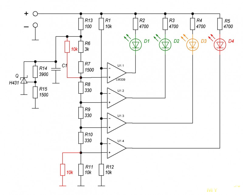
As a result of the refinement, the following response thresholds were obtained:
- red LED: 10.0 V (3.33 V per element, charging required);
- yellow LED: 10.6 V (3.53 V per element, charging is desirable);
- 1st green LED: 11.3 V (3.77 V per element, charge more than 50%);
- 2nd green LED: 12.0 V (4 V per element, battery fully charged).
If desired, it would be possible to choose better thresholds, but I am happy with this option.
Intended use
The object of modification was supposed to be such a PB. 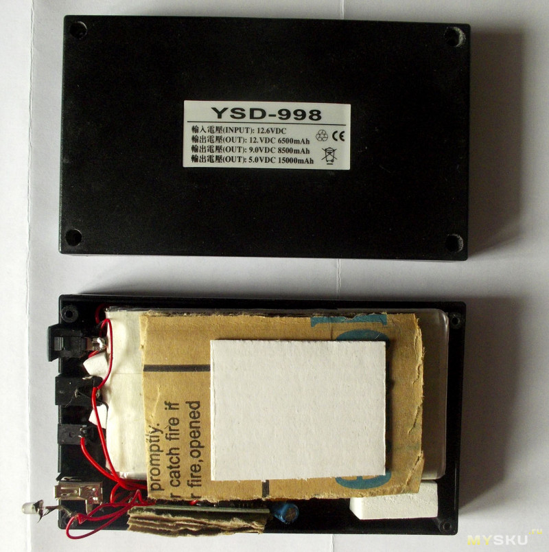
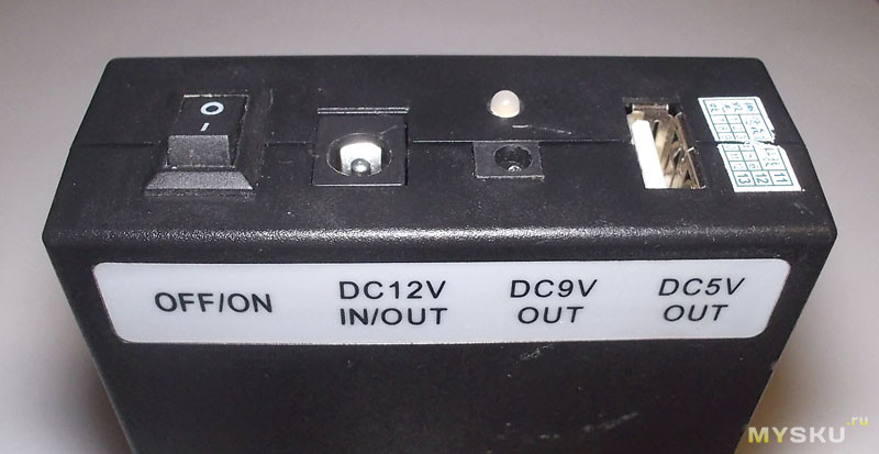
It was purchased back in '11, when the term power bank did not yet exist. There were just mobile batteries. I liked this model because it had a multivolt output (5, 9 and 12 V), was purchased and subsequently modified several times. The internals are similar to (in the same review there is a similar modification, only with a homemade board). Three flat batteries, each with its own protection, are connected in series and connected directly to the 12 V output/input. 9 V is made by a linear stabilizer. To obtain 5 V, a step-down board is used DC-DC converter. Through it, the PB produces 3500 mAh, which corresponds to the capacity of each element of about 1800 mAh. To prevent batteries from discharging during storage, they are mechanically switched off using a key switch. The only indicator is a two-color LED connected to the converter. Normal operation and overcurrent are displayed. 
All electronics are located next to the batteries, the free space is filled with “branded” pieces of Chinese cardboard. I pulled out everything that could be pulled out, tried on the board and the button that would connect it (so that it wouldn’t light up all the time). 
I made holes in the designated places. The burnt out LED also came in handy as a button. 
I installed it and soldered it. Initially, all connectors to the PB housing were secured with some kind of sealant. I didn't change the technology. It would be better to fix the button with hot glue or polymorphus so that it would not spring back, but I didn’t bother and just poured more sealant. It will harden after drying. Made it late in the evening, left it overnight open form. I collected it in the morning. 
Conclusions.
The board fully performs its functions. Lithium batteries require modification, but lead batteries can be used straight away. Another thing is that in devices with such batteries (car, UPS, controller solar battery) the indication is usually already there. In short, the board is in the category of “buy to keep lying around in your desk just in case.” If you have time, you can make such a circuit yourself or simply install a voltmeter.
I'm planning to buy +29 Add to favorites I liked the review +33 +577
SMD workshop No. 2! Battery charge level indicator for the motorist
Long-term operation of a car battery is achieved by maintaining it in a charged state. In this case, both overcharging and overdischarging the battery are harmful.
Car enthusiasts, especially those who are far from technology, find it convenient to simply assess the battery charge level according to the principle: “reduced”, “normal”, “increased”.
If we use LEDs for clarity different colors, you can assess the situation by glancing at the device.
The design is made on surface-mounted elements and is characterized by simplicity, low current consumption, sufficient accuracy in determining the technical condition of the battery and ease of reading the results.
The project is a continuation of the SMD workshop:
Schematic diagram of the battery voltage indicator
shown in Fig. 1, based on the diagram from.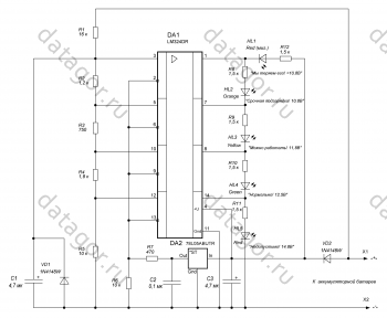
Rice. 1. Motorist indicator diagram
The device consists of a voltage divider R1 - R5, four comparators, which use a quad operational amplifier DA1, a reference voltage source DA2, which is a stabilizer with a fixed output voltage Uop = 5 V, and a five-level voltage indicator on multi-colored LEDs HL1 - HL5.
The voltage divider R1 – R5 provides the required operating thresholds of the comparators, selected as follows:
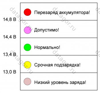
- more than 14.8 V– unacceptably high voltage (battery overcharging), which is dangerous due to boiling off of the electrolyte;
- 12.5…14.8 V– normally charged battery;
- 11.8…12.5 V– the remaining charge allows you to operate the battery (extend further discharge);
- 10.8…11.8 V– it is necessary to urgently recharge the battery to avoid sulfation;
- less than 10.8 V- “We are losing him.” It is necessary to restore the battery and resolve the issue of its further operation.
The indication device HL1 – HL5 is implemented in such a way that the activation of each subsequent cell causes the previous one to go out. Wherein two indicators are not illuminated at the same time.
For extreme (emergency) indication ranges, red LEDs HL1, HL5 are used.
For a range of less than 10.8 V, a flashing LED HL1 is used, and for more than 14.8 V, a regular HL5 is used.
Further, following the logic of the technical condition of the battery: HL2 - orange LED, HL3 - yellow and HL4 - green (normal).
Resistors R8 – R11 are current limiting. The current-limiting resistor R12 for the flashing LED HL1 is, in principle, not needed, but does not interfere with its operation and allows you to install a regular LED if necessary.
Specified on schematic diagram rice. 1 The ratings of the divider R1 – R5 provide sufficient accuracy of operation of the comparators for the above threshold voltages and reference voltage Uop=5 V.
The front panel of the indicator is shown in Fig. 2.
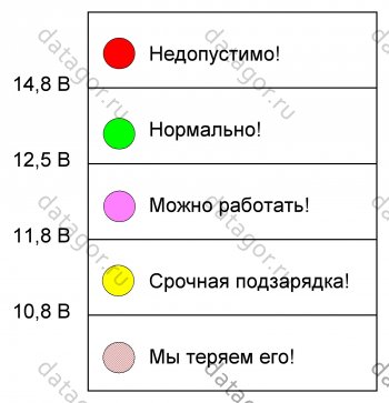
Rice. 2. Front panel indicator
The calculation of the voltage divider is given in the attached file " Divisor calculation.xls».
If necessary, the divider can be easily recalculated by indicating other required thresholds for the comparators.
For example, the device response thresholds, selected based on the experience of experienced auto electricians, are shown in Fig. 3.
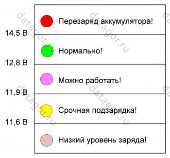
Rice. 3. Another option for the front indicator panel
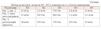
Divider resistors R1 – R5 can be recalculated to control the battery with the car engine running (Fig. 4).
Rice. 4. Indicator response threshold levels for monitoring the battery while the engine is running
The table shows the parameters of the divider resistors R1 – R5 for the implementation of the three indicator applications indicated above.
Resistor R7 sets the exact value of the reference voltage Uop = 5 V, caused by the spread of the output voltage integral stabilizer DA2 to the larger side.
When using a probe, you cannot ignore Murphy's law, which dictates that everything that can be confused will be confused. Everything that cannot be confused will also be confused.
To protect against incorrect connection of the indicator to the battery, diodes VD1 and VD2 are installed.
Diode VD1, bypassing blocking capacitor C1, prevents its polarity reversal and also protects the inputs of DA1. Diode VD2 protects the power circuit of microcircuits DA1 and DA2.
Now “polarity reversal” is completely harmless to the indicator.
Motorist indicator parameters:
Input voltage range: 6…20 V;
Current consumption: 15 mA.
Indicator details
All SMD resistors are convenient for installation in standard size 1206. Divider resistors R1 – R5 have an accuracy of 1%, the rest - 5%.Capacitors C1, C3 are tantalum, size B, for a voltage of 25 V, C2 is ceramic.
LED HL1 – red flashing, HL2 – HL5 almost any required colors.
I used regular LEDs, but the printed circuit board allows you to install surface-mount elements.
Parts List:
DA1 – LM324DR operational amplifier chip, SO-14 package – 1 pc.,
DA2 – +5 V stabilizer chip 78L05ABDR2, housing SO8-150-1.27 – 1 pc.,
VD1, VD2 – Diode 1N4148W, SOD-123 housing – 2 pcs.,
HL1 – LED DFL-3014SRC-B, cr. moment. d=3 mm – 1 pc.,
HL2 – LED KIPD66ZH-R, orange. d=3 mm – 1 pc.,
HL3 – LED KIPD66A-Zh; yellow d=3 mm – 1 pc.,
HL4 – LED BL-BG3331K, green. d=3 mm – 1 pc.,
HL5 – LED 354ED red. d=3 mm – 1 pc.,
R1 – Chip resistor F1206-16 kOhm – 1 pc.,
R2 – Chip resistor F1206-1.2 kOhm – 1 pc.,
R3 – Chip resistor F1206-750 Ohm – 1 pc.,
R4 – Chip resistor F1206-1.8 kOhm – 1 pc.,
R5, R6 – Chip resistor F1206-10 kOhm – 2 pcs.,
R7 – Chip resistor J1206-470 Ohm (selected during setup) – 1 pc.,
R8 – R12 – Chip resistor J1206-1.5 kOhm – 5 pcs.,
C1, C2 – Capacitor 4.7/25V tantalum B – 2 pcs.,
C3 – Capacitor 1206 0.1µF-Y5V 80-20% CHIP – 1 pc.,
Printed circuit board 38×30 mm.
Indicator assembly
The printed circuit board with the placement of elements is shown in Fig. 5.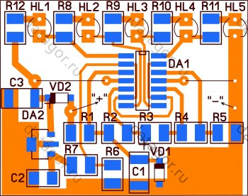
Rice. 5. View printed tracks and placement of elements on the printed circuit board
First, all elements are installed, with the exception of resistor R7, which is selected during setup. All elements, except two jumpers, are installed on the side of the printed tracks.
Setting up a voltage indicator
To set up, you will need a regulated power source.During setup, it is advisable to switch on a 1 kOhm variable resistor in place of resistor R7 as a rheostat.
Using an adjustable power source, the voltage is set to 14.8 V, and by rotating the variable resistor knob, the HL5 LED starts to ignite.
Measure the resistance of the working part of the resistor and install a resistor of the closest value in place of R7.
Next, check other indicator thresholds and make sure they correspond to the selected ones.
When the tolerance of resistors R1 - R5 is 1%, clarification of the divider resistance is usually not required.
Results
The SMD workshop offered allows you to gain experience in creating a reliable and useful design.It is recommended to monitor the condition of the car battery at least twice a year (in spring and autumn). Timely bringing the battery into working condition extends its service life.
The appearance of the assembled battery charge level indicator is shown in the introductory part of the article.
Files
Scheme printed circuit board and the file with the calculation of the divisor can be found here:▼ ⚖ 38.23 Kb ⋅ ⇣ 45 Hello! My name is Igor Kotov, I’m 44, I’m a native Siberian and an avid amateur electronics engineer. I came up with, created and have been maintaining this site since 2006.
For more than 10 years, our site has existed only at my expense.
Monthly expenses for editorial needs currently amount to about 25 thousand rubles.
The minimum required is 75€ at the monthly rate to rent a dedicated server.
We have hard times. I am simply not able to “pull” alone.
That's why we were forced lead