How to convert a monitor to LEDs. LCD backlight
CCFLor LED?
The actively developing LED industry could not help but influence the LCD display industry; now it no longer matters whether it is the screen of a phone, tablet, laptop, monitor or TV. LED or, in other words, LED backlighting of matrices has almost completely replaced backlighting on CCFL and EEFL lamps. And this is quite logical; LED backlighting has significantly more advantages, such as high efficiency, long service life, no mercury, no fading and a wide color gamut.
But what to do if your laptop has a CCFL backlight and it fails? Should I reinstall the CCFL lamp or replace it with LED backlighting? My advice is the following: if this laptop is dear to you, and you do not plan to sell or give it away after repair, then it is better to install LED backlighting and forever forget about the problem of CCFL lamps burning out. Yes, in some cases it can be a little more expensive, and replacement requires some technical skills, but in this article I will try to talk about one of the ready-made kits for such modification of your laptop screen, which can help you when choosing and installing a kit.
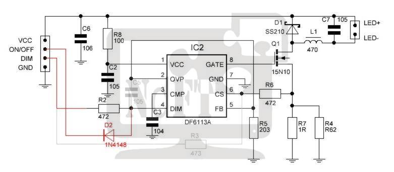
Features of the LED set CA backlight-166 and circuit design
The location of the inductance indicates that it is built on the principle of a step-down DC-DC converter, hence the limitation on the minimum input voltage that was mentioned earlier. To operate the backlight, you need a voltage equal to the power supply for 3 serial LEDs (average 9.6V) + 420mV voltage feedback. Therefore, the supply voltage must be no lower than 10V and no more than 24V (chip limitation). Resistors R4 and R7 are used to set the operating current LED backlight. The current strength is chosen on the basis that one section of three diodes at maximum brightness consumes about 20 mA. And based on these data, it is calculated using the formula Imax = 420mV/Rout. The table below shows recommended resistance values.
|
Diagonal, inch |
Tape length, mm |
Number of diodes, pcs |
|
|
15" square |
|||
|
14" wide |
|||
|
14" square |
|||
|
13.3” wide |
|||
|
12" square |
|||
|
12" wide |
|||
Using larger resistors will not damage the LEDs, but will only reduce the maximum brightness. Installing resistors of a lower value is also possible, but it is necessary to enable the brightness adjustment function of the laptop.
Brightness adjustment is analog and occurs by changing the voltage level at the DIM pin. This decision was made in order to increase the versatility of the device, since when using this backlight in laptops with PWM brightness control, it will also work, but perhaps the brightness level will not be adjusted within wide enough limits. If you are not satisfied with the resulting brightness adjustment range, you can make simple modifications described below.
Revision 1. LED modificationbacklight for working with a PWM brightness control signal
This modification will allow us to somewhat expand the range of brightness adjustment and better adapt the board to work with a PWM control signal.
Below is a diagram in which red lines indicate introduced elements and connections, and gray lines indicate removed elements and connections
Scheme of changes in the LED backlight driver for working with a PWM brightness control signal
For modification you will need
Diode 1N4148 or similar (in SMD SOD-323* package)
Resistor 2.2 Ohm** (SMD 1206)
Resistor 3.0 Ohm** (SMD 1206)
*The specified types of housings are not mandatory, but are recommended because they are very convenient to install on the board.
**Resistor values were chosen for reasons of gentle operation of the LED backlight. If necessary, you can use the resistance values from the table given earlier.
- Remove C5
- Remove R3
- Replace current resistors R4 and R7. Instead of 2 resistors, you can install one at 1.3 ohms, and the maximum brightness will decrease slightly.
- Install the 1N4148 diode diagonally, with the cathode to the left terminal of resistor R3, and the anode to the lower terminal of capacitor C5.
The photo below clearly shows the changes to the LED driver board. The places of change are outlined in red.
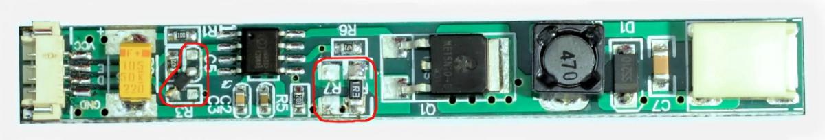
After this modification, the DIM input will be fully compatible with the PWM brightness signal. The turn-on signal input is also fully PWM compatible. The current supplied by the driver at maximum brightness will be approximately 320mA. The minimum brightness depends on the duty cycle of the PWM signal. With a common PWM frequency of 60Hz, the minimum brightness will be about 36mA, which corresponds to a brightness adjustment of 1:9. Since the PWM signal frequency in most laptops is only 60 Hz, some people may notice a slight flicker. If you need to get rid of it, then I recommend taking a look at the next modification, which is free of this drawback.
Improvement 2. Remove the influence of the PWM signal on the image
This modification is somewhat more complicated compared to the previous one, but gives more noticeable results. With this modification, it is possible to completely get rid of brightness modulation, increase conversion efficiency, and expand the brightness adjustment range up to 1:100.
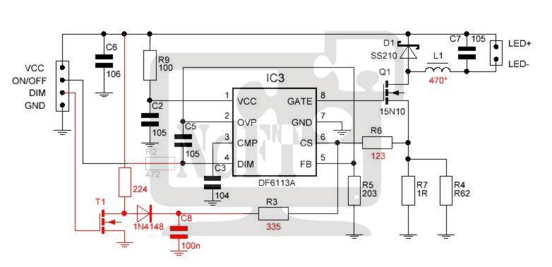
Below is a diagram with the indicated modifications
For modification you will need
1n4148 diode (or similar in DO35* package)
Resistor 220kΩ 1% accuracy
Resistor 12kΩ (SMD 0603)
Resistor 330kΩ (SMD 0603)
Capacitor 25V 0.1µF (SMD 0603 MLCC)
N-channel MOSFET (ZVN2106A, 2N7000 or similar)
Resistor 1.8** Ohm (SMD 1206)
Resistor 3.9** Ohm (SMD 1206)
If it is necessary to expand the range of brightness adjustment, then you will also need to replace the inductance L1, the value of which is selected based on the requirements for brightness adjustment. The dependence of the brightness range on inductance is given in the following table:
*The given packaging of elements was chosen for reasons of ease of installation and is not a mandatory requirement.
**Resistor values are selected according to the length and current consumed by the LED backlight. See table above.
Sequence of actions during revision
- Remove capacitor C5.
- Remove resistor R3.
- Replace current measuring resistors R4 and R7 with resistors 1.8 Ohm and 3.9 Ohm (or those selected from the table).
- If necessary, replace inductance L1 - 47µH with a larger inductance value. This will reduce the minimum settable output current from 16 mA to 8 mA.
- Replace resistor R6 with a resistor with a value of 12 kOhm.
- Solder a 330 kOhm resistor with one leg to pin 6 of the DF6113 chip.
- Solder a 0.1µF capacitor to leg 7 of the DF6113 microcircuit.
- Connect the free leads of the resistor from step 6 and the capacitor from step 7 together.
- Solder the source field effect transistor to the ground terminal of resistor R5.
- Solder the drain of the FET to the anode of the 1N4148 diode.
- Connect the cathode of the 1N4148 diode at the point formed between the resistor and capacitor from step 8.
- Connect the terminal of the 220 kΩ resistor to the positive terminal of the input tantalum capacitor C6. Connect the second pin to the drain of the transistor, this is the pin to which we previously connected the anode of the 1N4148 diode.
- Solder the gate of the transistor to the left pad of resistor R3.
When using surface mount components, be extremely careful to avoid short circuit between the conclusions.
The location of the parts can be seen in the following pictures:
After such modification, the PWM brightness control signal will be converted to analog. This will eliminate possible flicker, lead to a more linear brightness adjustment and expand the range of its adjustment.
Conclusion
The considered LED backlight set, which is designed specifically to replace CCFL in laptop screens, has a number of advantages that compensate for some installation complexity. The advantages include the set's affordability, durability, improved color rendition, etc. Although the given design of the LED backlight driver board does not realize all the advantages of the DF6113 chip, this can be easily fixed if you have a couple of common radio elements and a soldering iron.
A kit for replacing the old CCFL backlight of a laptop matrix with LED can be purchased in our store at this link
Description:
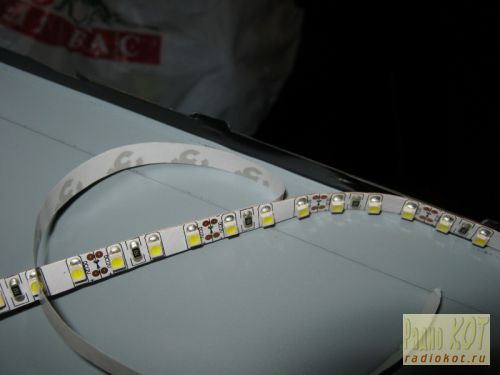
It is better to take a tape with a neutral white glow, and its width should be minimally narrow (the width of the tape in the photo is 8 mm). The number of LEDs is also important - at least 120 LEDs per meter of strip.
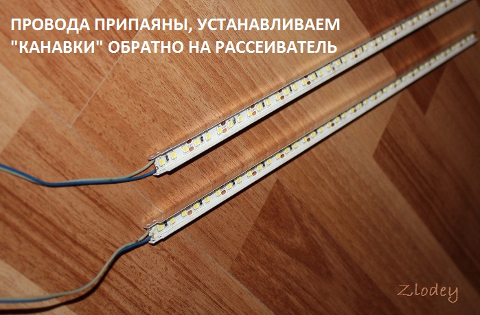

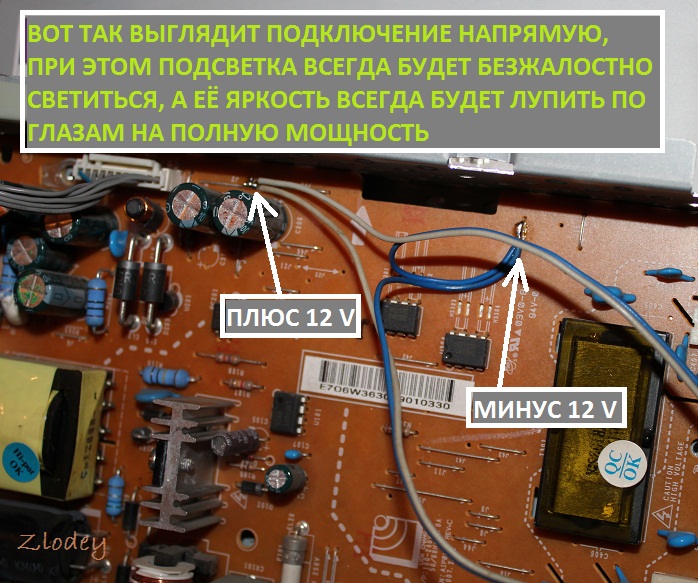
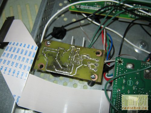
On the board you can find jumpers that contain 12 volt power, and solder the backlight wires to these jumpers.
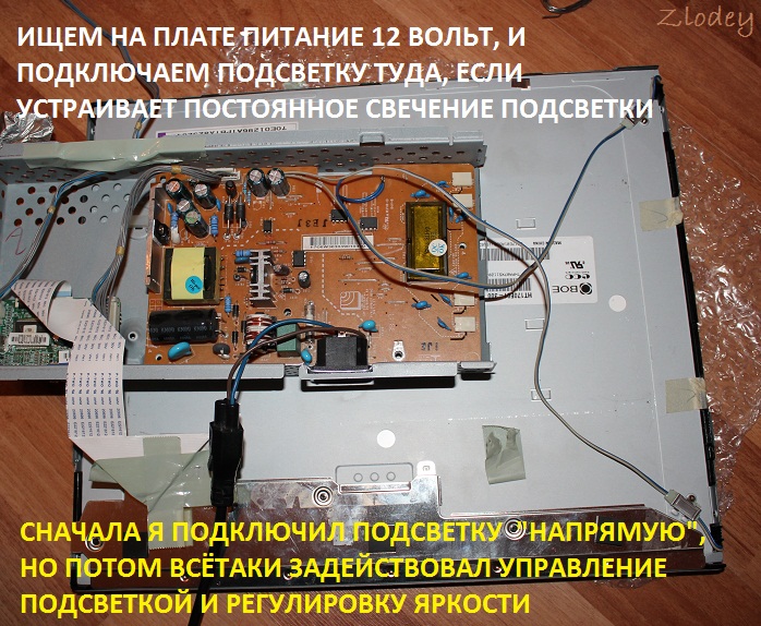
After this modification, a problem appears - the backlight is constantly on, and even the brightness is not adjustable... Let's start looking for the backlight brightness adjustment circuit. We carefully look at the inscriptions near the connector. The "ON" pin turns the backlight on and off; when the backlight is on, there is a voltage of about 3 volts at the "ON" pin. When the backlight is off, there is no voltage at the "ON" pin. The "DIM" pin adjusts the backlight brightness by changing the duty cycle of the PWM signal. When setting almost maximum brightness, the PWM duty cycle is 80...90%, the signal amplitude is 5 volts. When the backlight is turned off, there is also no signal at the "DIM" output, so there is no need to use the "ON" pin. To turn it on/off and adjust the brightness, it is enough to use the "DIM" pin. In order to adjust the brightness, you need to connect the LED strip through an N-channel field switch, and apply a signal from the “DIM” pin to the gate of the field switch through a small resistor (100...200 ohms).
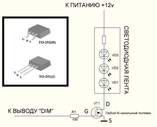
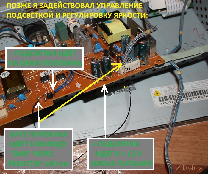
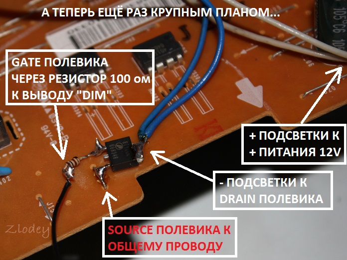
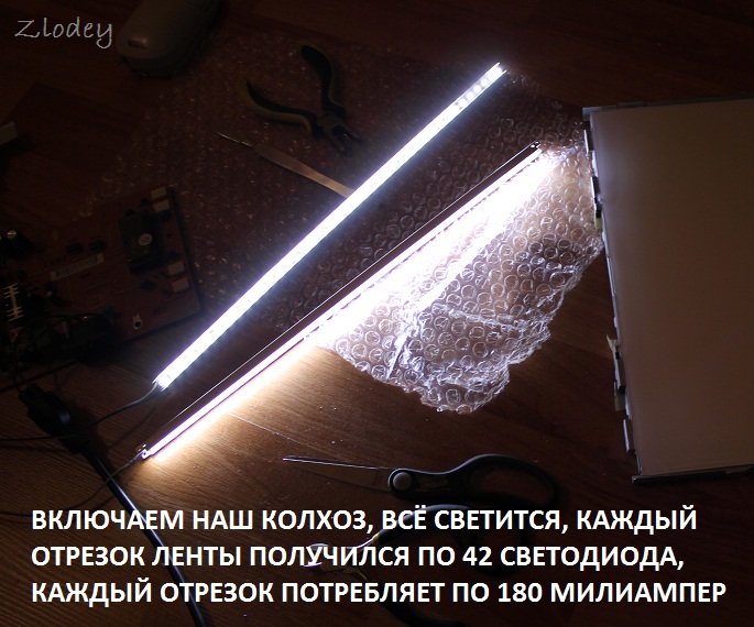
I took the field switch from a burned out motherboard, N-channel AP9T18GH, with a maximum drain-source voltage of 20 volts and a current of 10 amperes. By the way, each of the tape segments consumes approximately 180 milliamps, so you can use almost any field device with a current of at least 0.5 amperes. Also, just for fun, I measured the supply voltage along the 12 volt circuit. The voltage was within normal limits.
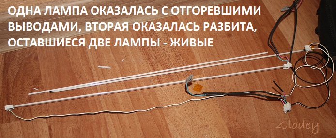
Time passes unnoticed and seemingly recently purchased equipment is already breaking down. So, having worked their 10,000 hours, the lamps of my monitor (AOC 2216Sa) gave up their life. At first, the backlight did not turn on the first time (after turning on the monitor, the backlight turned off after a few seconds), which was solved by turning the monitor on/off again; over time, the monitor had to be turned off/off 3 times, then 5, then 10, and at some point it could not turn on the backlight, regardless of the number of attempts to turn it on. The lamps brought to the light of day turned out to have blackened edges and were legally thrown into scrap. An attempt to install replacement lamps (new lamps of the appropriate size were purchased) was unsuccessful (the monitor was able to turn on the backlight several times, but quickly went into on-off mode again) and finding out the reasons for what the problem could be in the electronics of the monitor led me to the idea that it will be easier to assemble your own monitor backlight using LEDs than to repair the existing inverter circuit for CCFL lamps, especially since there have already been articles on the Internet showing the fundamental possibility of such a replacement.
Disassembling the monitor
Many articles have already been written on the topic of disassembling a monitor; all monitors are very similar to each other, so in brief:
1. Unscrew the monitor delivery mount and the only bolt at the bottom that holds the back wall of the case 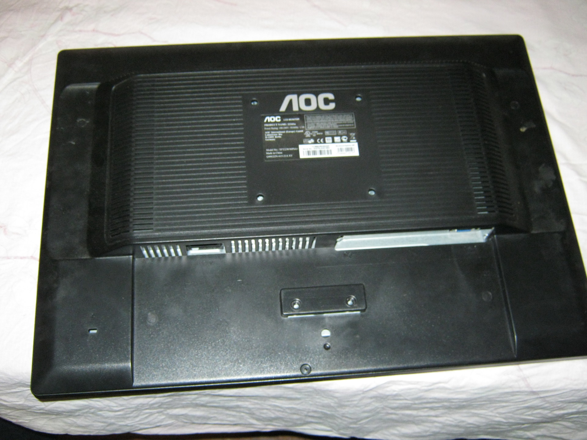
2. At the bottom of the case there are two grooves between the front and back of the case, insert a flat-head screwdriver into one of them and begin to remove the cover from the latches along the entire perimeter of the monitor (simply turning the screwdriver carefully around its axis and thereby lifting the case cover). There is no need to exert excessive effort, but it is difficult to remove the case from the latches only the first time (during the repair I opened it many times, so the latches became much easier to remove over time).
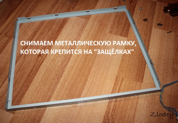
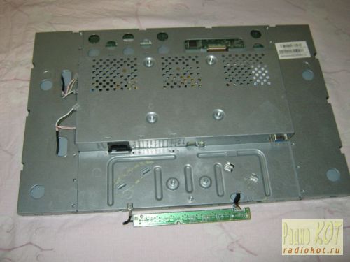
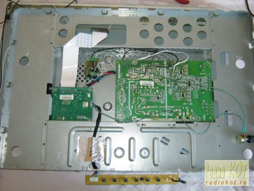
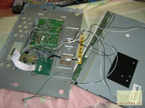
3. We have a view of the installation of the internal metal frame in the front of the case: 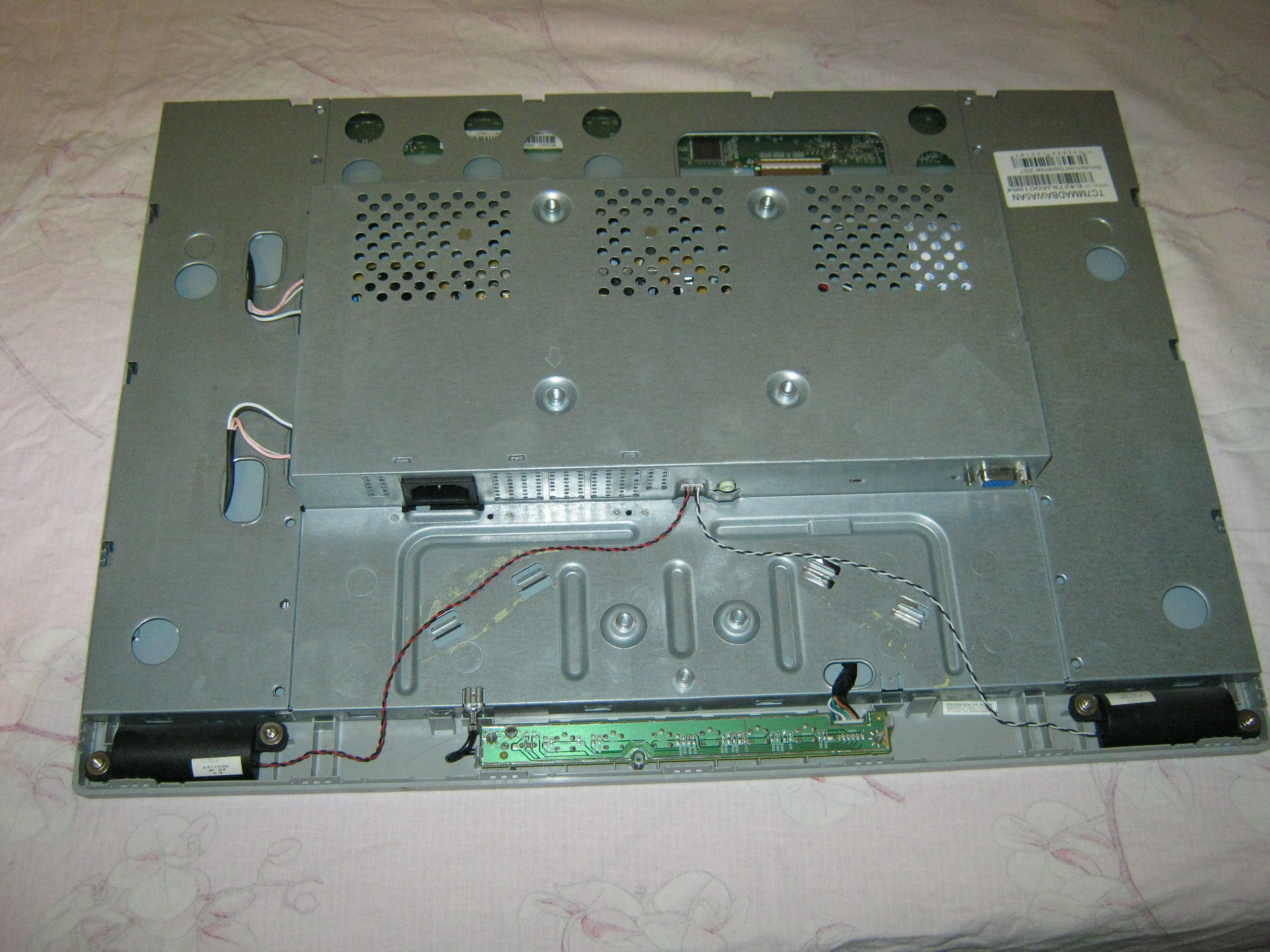
We take out the board with the buttons from the latches, take out (in my case) the speaker connector and, bending the two latches at the bottom, take out the inner metal case.
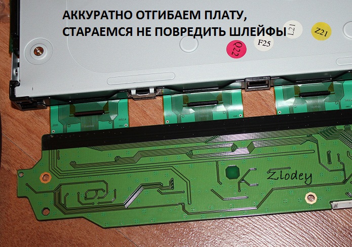
4. On the left you can see 4 wires connecting the backlight lamps. We take them out by squeezing them slightly, because... To prevent it from falling out, the connector is made in the form of a small clothespin. We also remove the wide cable going to the matrix (at the top of the monitor), squeezing its connector on the sides (since the connector has side latches, although this is not obvious at first glance at the connector): 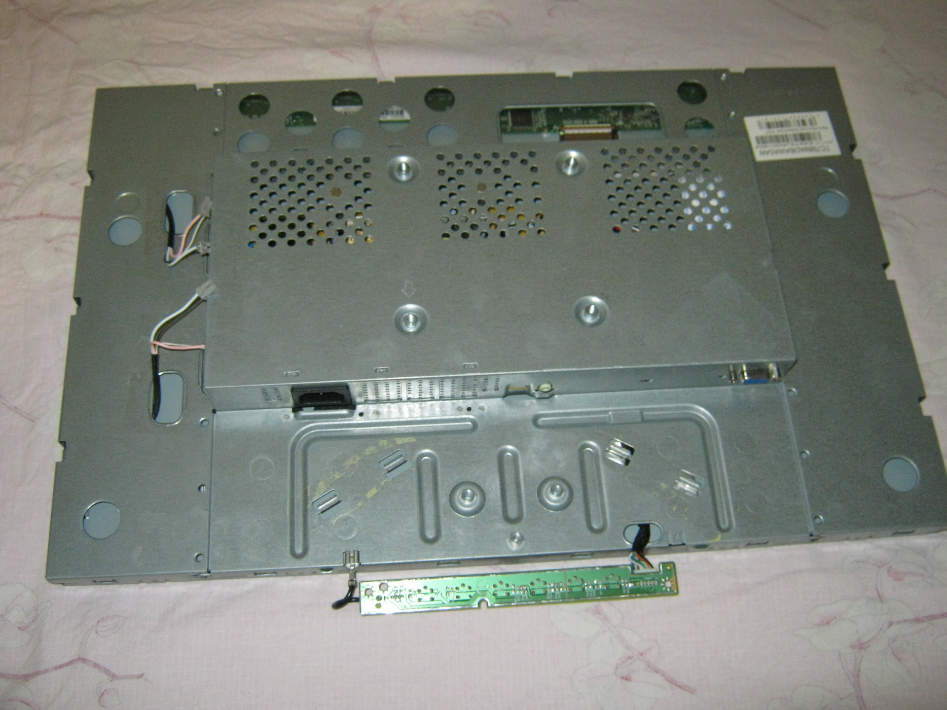
5. Now you need to disassemble the “sandwich” containing the matrix itself and the backlight: 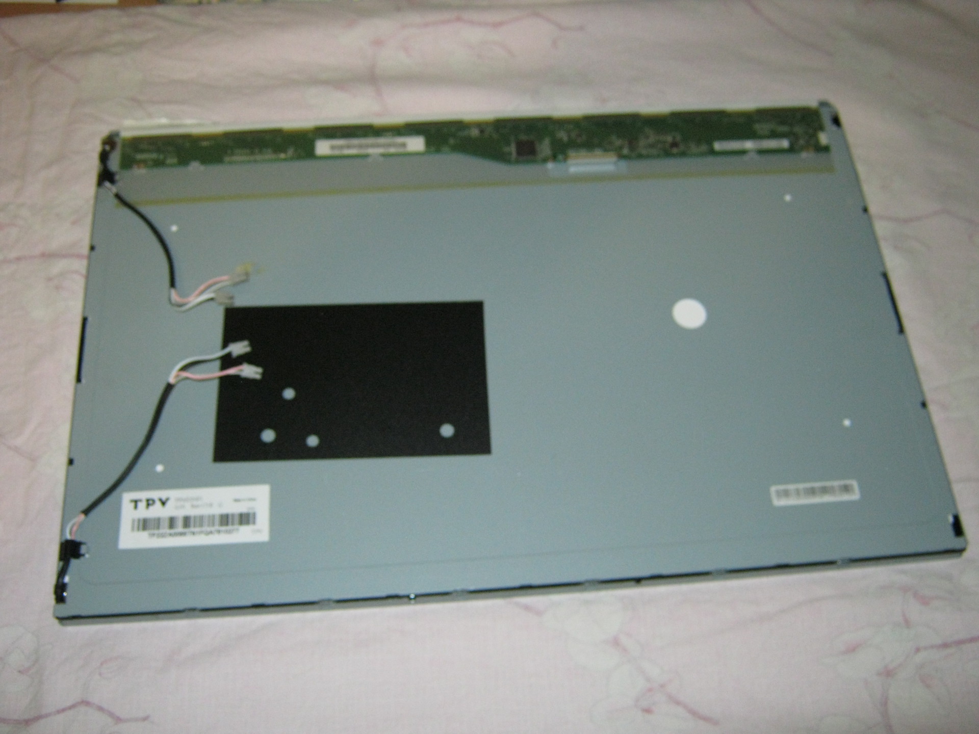
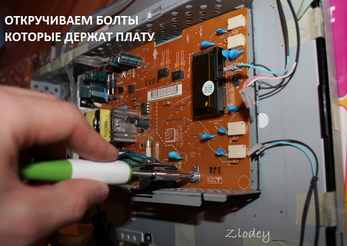
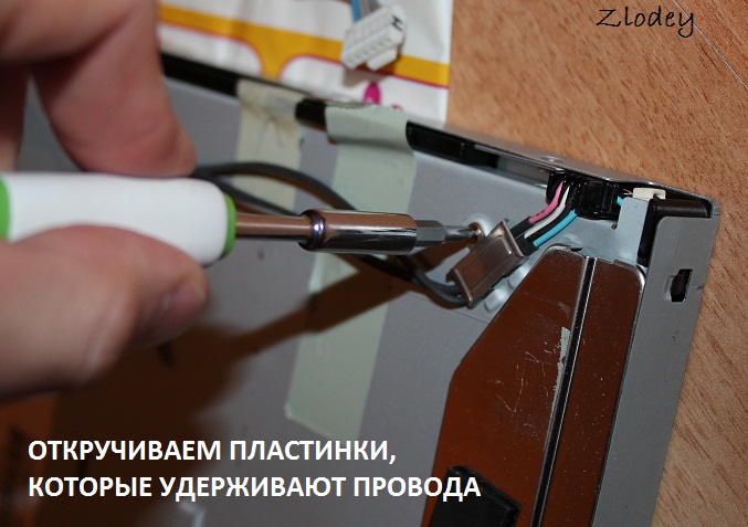
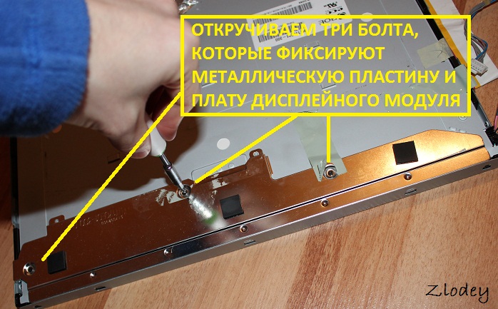
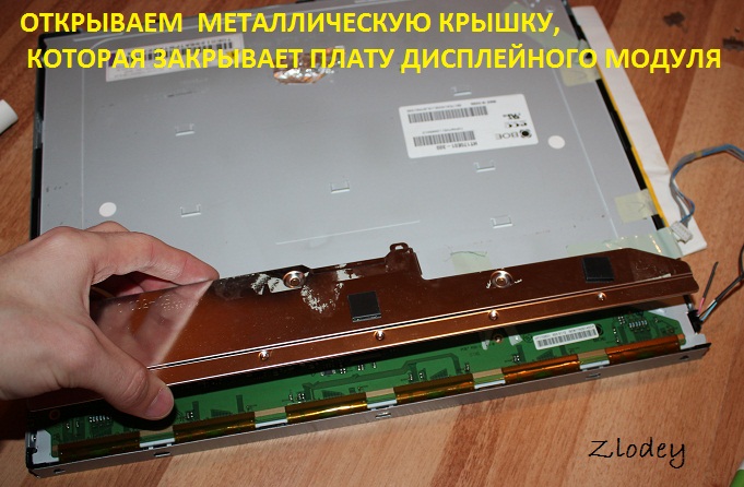
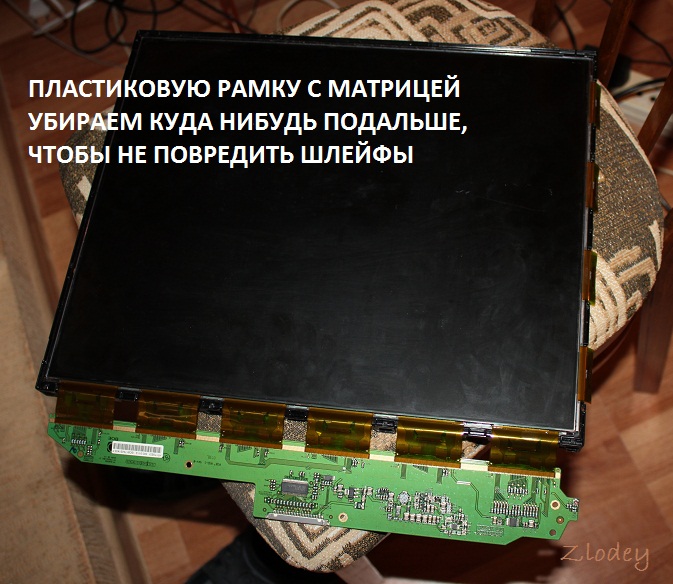
There are latches along the perimeter that can be opened by lightly prying with the same flat screwdriver. First, the metal frame holding the matrix is removed, after which you can unscrew three small bolts (a regular Phillips screwdriver will not work due to their miniature size, you will need a particularly small one) holding the matrix control board and the matrix can be removed (it is best to place the monitor on a hard surface, such as a table covered with the fabric facing down, unscrew the control board, place it on the table, unfolding it through the end of the monitor, and simply lift the backlit case, lifting it vertically up, and the matrix will remain lying on the table. It can be covered with something so as not to gather dust, and assembled exactly the opposite way. order - i.e. cover the matrix lying on the table with the assembled case with backlight, wrap the cable through the end to the control board and, screwing the control board, carefully lift the assembled unit).
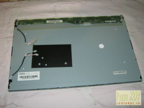
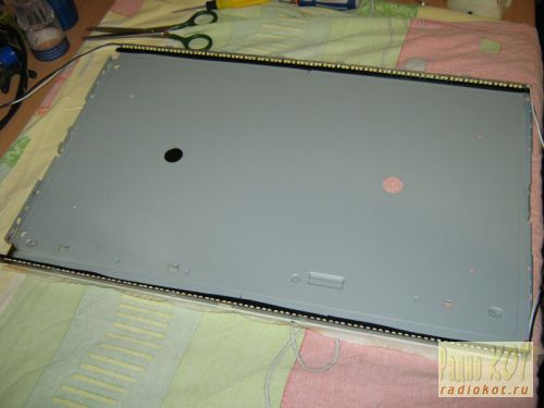
The matrix is obtained separately: 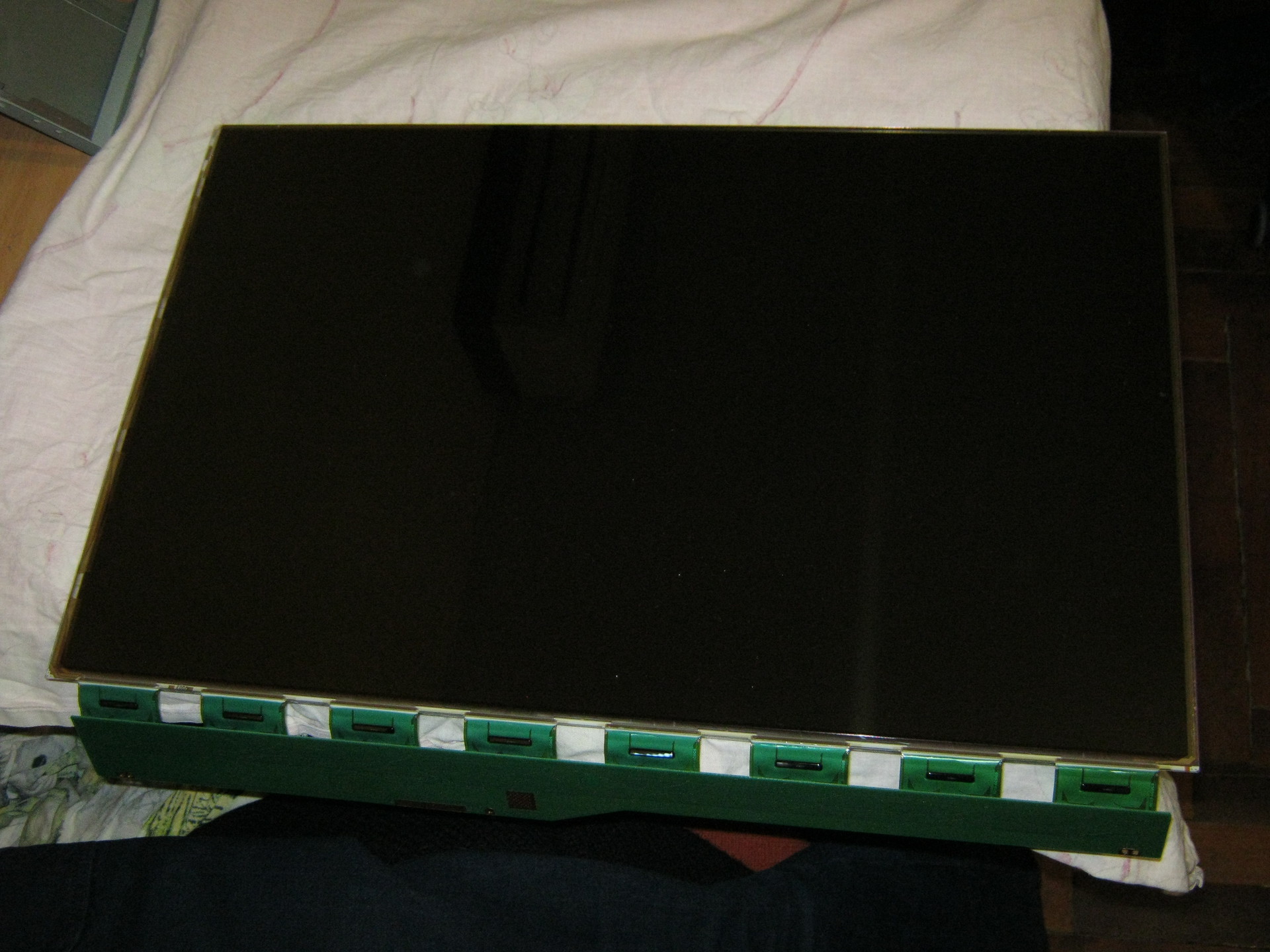
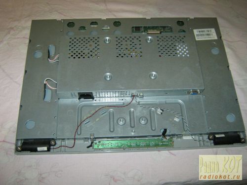
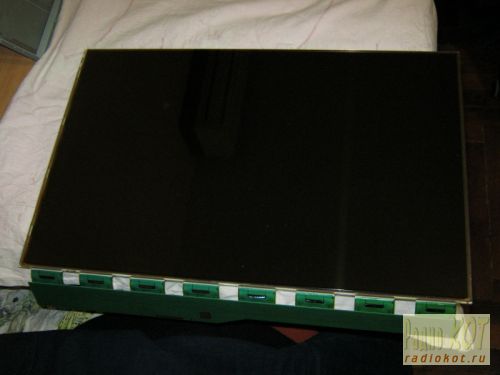
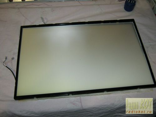
And the backlit block separately: 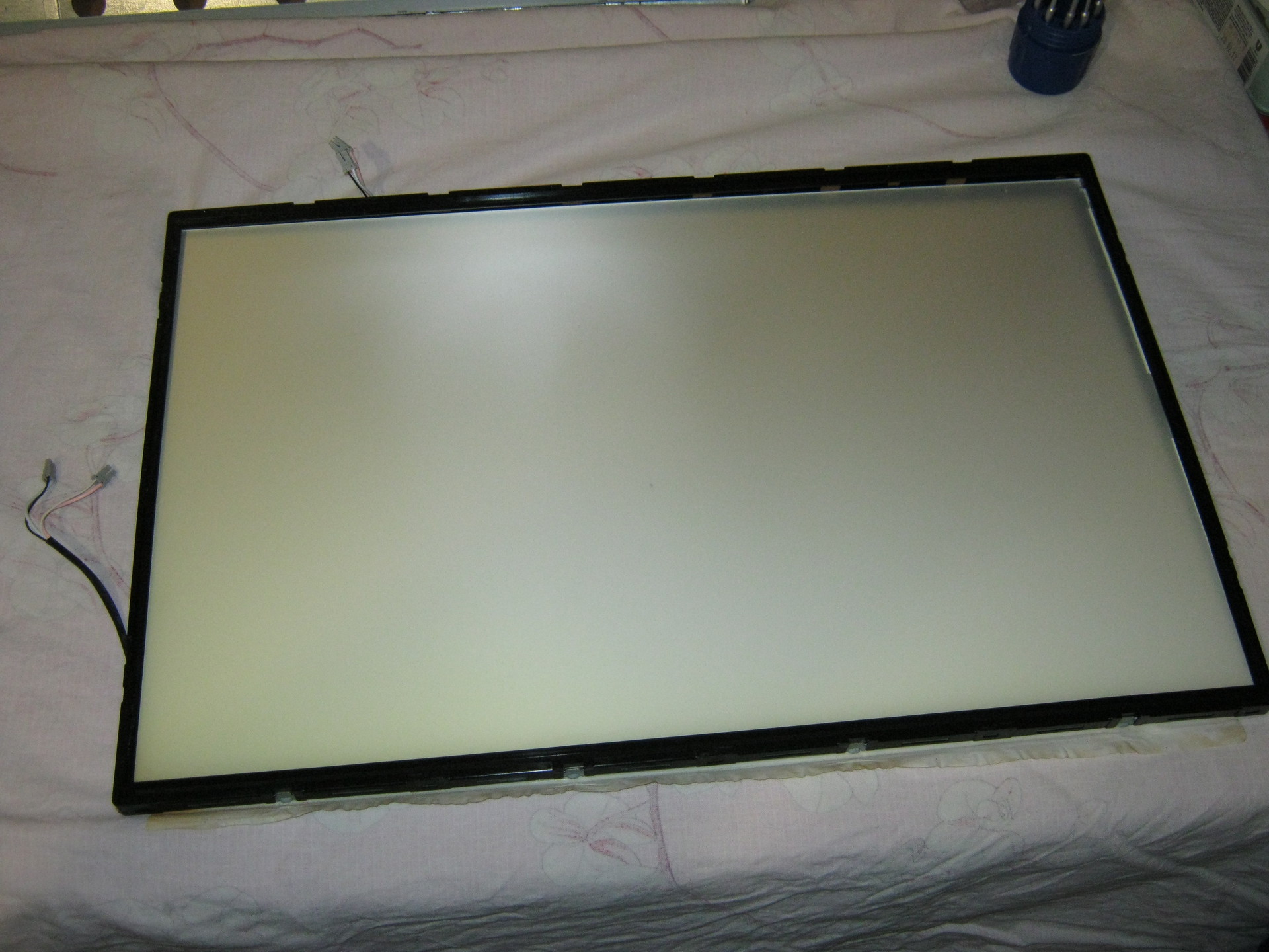
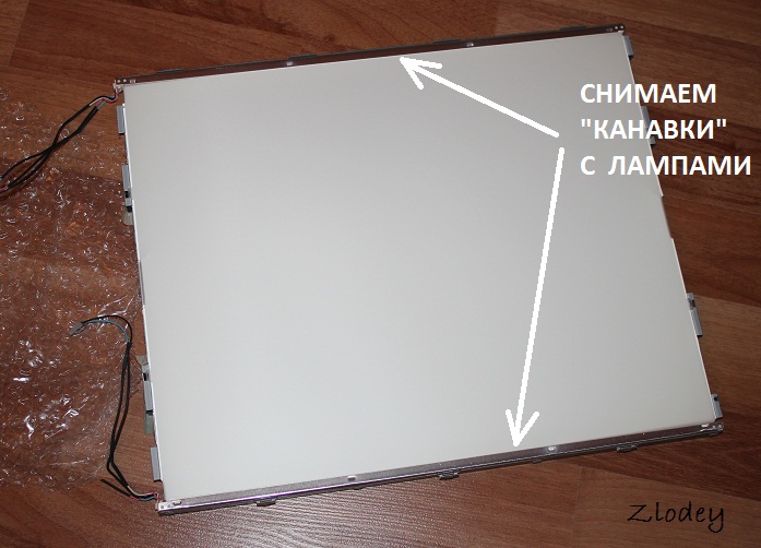
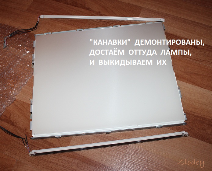
The backlit unit is disassembled in the same way, only instead of a metal frame, the backlight is held by a plastic frame, which simultaneously positions the plexiglass used to diffuse the backlight light. Most of the latches are located on the sides and are similar to those that held the metal frame of the matrix (they open by prying them off with a flat-head screwdriver), but on the sides there are several latches that open “inward” (you need to press on them with a screwdriver so that the latches go inside the case).
At first I remembered the position of all the parts to be removed, but then it turned out that it would not be possible to assemble them “wrongly” and even if the parts look absolutely symmetrical, the distances between the latches on different sides of the metal frame and the locking protrusions on the sides of the plastic frame holding the backlight will not allow them to be assembled “wrongly” "
That's all - we disassembled the monitor.
LED strip lighting
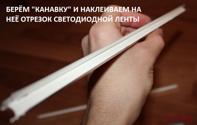
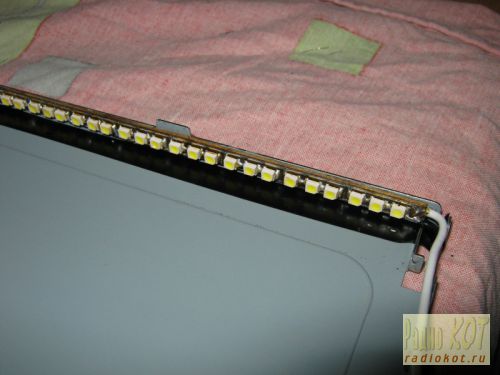
At first, it was decided to make the backlight from an LED strip with white LEDs 3528 - 120 LEDs per meter. The first thing that turned out to be is that the width of the tape is 9 mm, and the width of the backlight lamps (and the seat for the tape) is 7 mm (in fact, there are backlight lamps of two standards - 9 mm and 7 mm, but in my case they were 7 mm). Therefore, after examining the tape, it was decided to cut 1 mm from each edge of the tape, because this did not affect the conductive paths on the front part of the tape (and on the back, along the entire tape, there are two wide power cores, which will not lose their properties due to a decrease of 1 mm over a backlight length of 475 mm, since the current will be small). No sooner said than done: 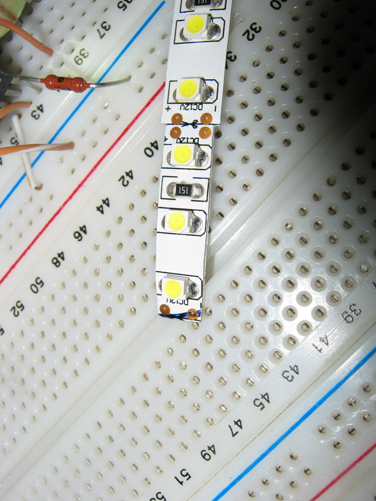
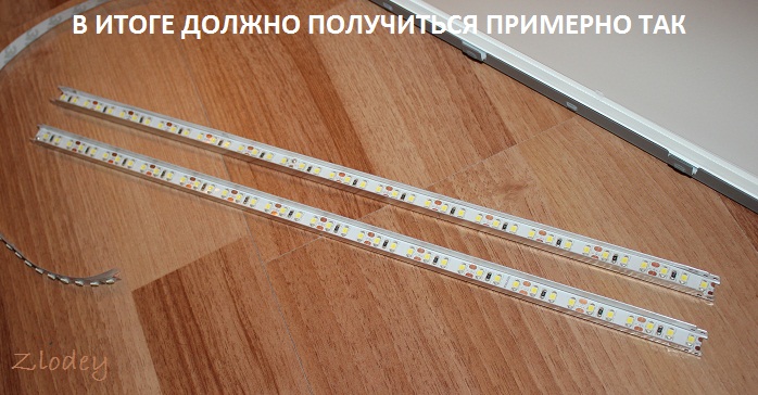
Just as neat LED Strip Light trimmed along the entire length (the photo shows an example of what happened before and what happened after trimming).
We will need two strips of 475 mm tape (19 segments of 3 LEDs per strip).
I wanted the monitor backlight to work the same way as the standard one (i.e. it was turned on and off by the monitor controller), but I wanted to adjust the brightness “manually”, as on old CRT monitors, because This is a frequently used function, and I got tired of navigating through on-screen menus pressing several keys every time (on my monitor, the right-left keys do not adjust the monitor modes, but the volume of the built-in speakers, so the modes had to be changed through the menu every time). To do this, I found a manual for my monitor on the Internet (for those who need it, it is attached at the end of the article) and on the page with the Power Board, according to the diagram, +12V, On, Dim and GND were found that are of interest to us. 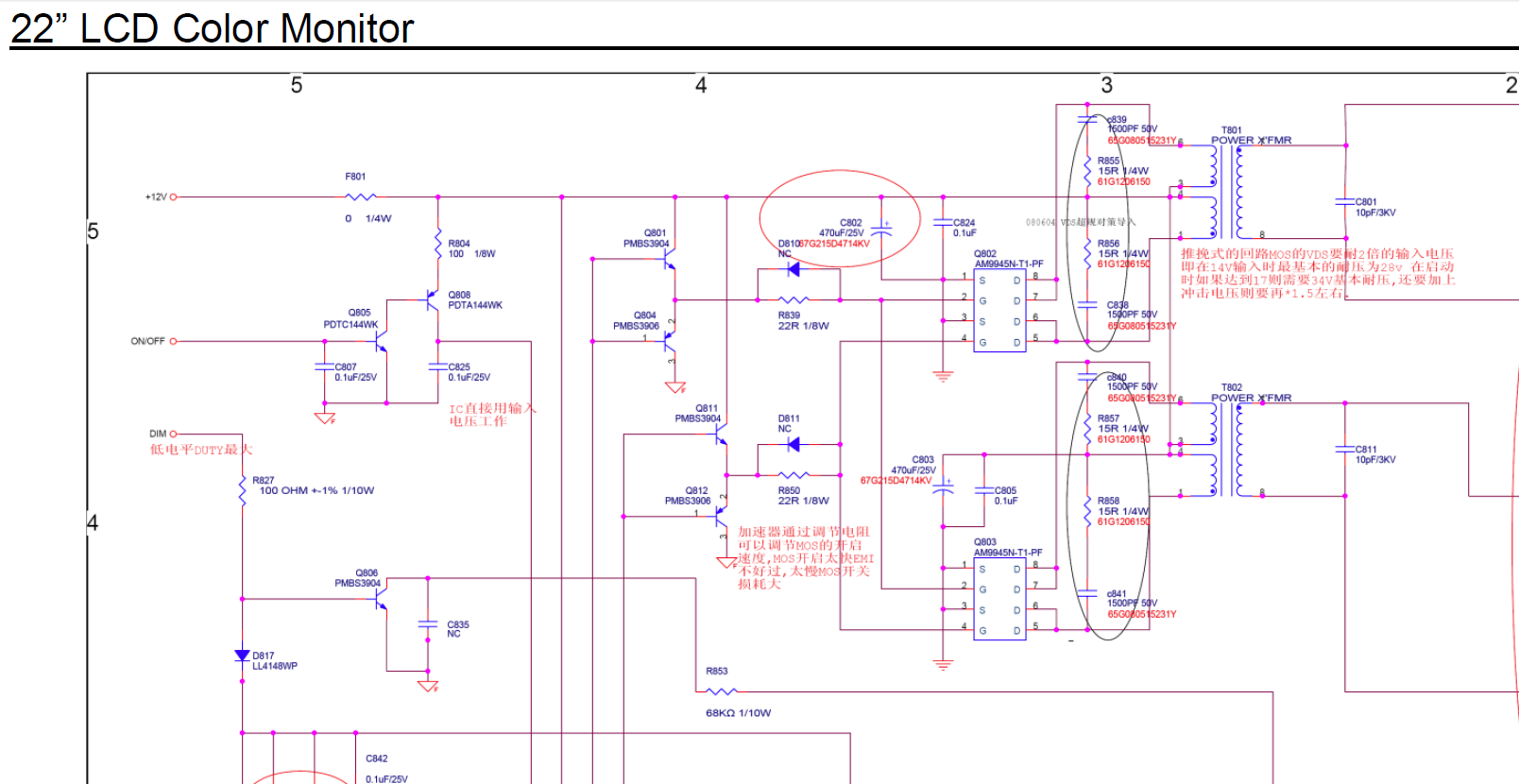
On - signal from the control board to turn on the backlight (+5V)
Dim - PWM backlight brightness control
+12V turned out to be far from 12, but somewhere around 16V without backlight load and somewhere around 13.67V with load
It was also decided not to make any PWM adjustments to the backlight brightness, but to power the backlight with direct current (at the same time, the issue is resolved that on some monitors the PWM backlight operates at a not very high frequency and for some this makes their eyes a little more tired). In my monitor, the “native” PWM frequency was 240 Hz.
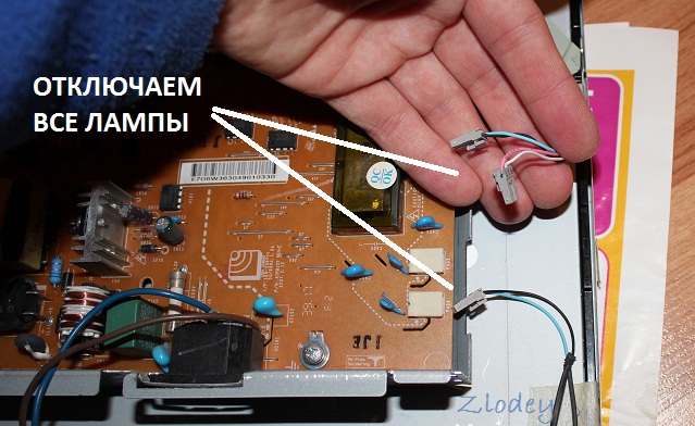
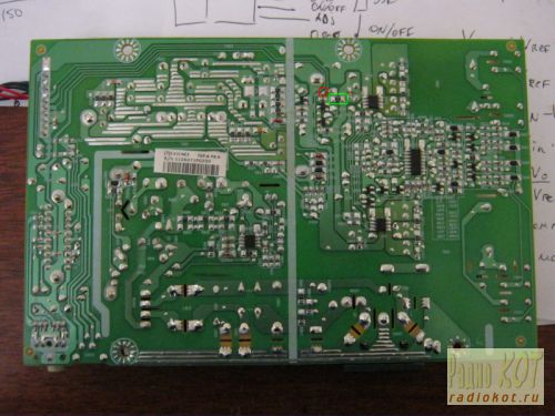
Further on the board we found contacts to which the On signal is sent (marked in red) and +12V to the inverter unit (the jumper that must be pulled out to de-energize the inverter unit is marked in green). (photo can be enlarged to see notes): ![]()
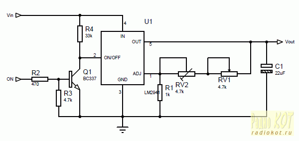
The LM2941 linear regulator was used as the basis for the control circuit, mainly because at a current of up to 1A it had a separate On/Off control pin, which was supposed to be used to control the backlight on/off with the On signal from the monitor control board. True, in LM2941 this signal is inverted (that is, there is voltage at the output when the On/Off input is zero potential), so we had to assemble an inverter on one transistor to match the direct On signal from the control board and the inverted input of LM2941. The scheme does not contain any other excesses: 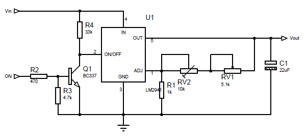
The output voltage for LM2941 is calculated using the formula:
Vout = Vref * (R1+R2)/R1
where Vref = 1.275V, R1 in the formula corresponds to R1 on the circuit, and R2 in the formula corresponds to a pair of resistors RV1+RV2 on the circuit (two resistors are introduced for more smooth adjustment brightness and reducing the range of voltages regulated by variable resistor RV1).
I took 1kOhm as R1, and the selection of R2 is carried out according to the formula:
R2=R1*(Vout/Vref-1)
The maximum voltage we need for the tape is 13V (I took a little more than the nominal 12V so as not to lose brightness, and the tape will survive such a slight overvoltage). Those. maximum value R2 = 1000*(13/1.275-1) = 9.91 kOhm. The minimum voltage at which the tape still glows at least somehow is about 7 volts, i.e. minimum value R2 = 1000*(7/1.275-1) = 4.49 kOhm. Our R2 consists of a variable resistor RV1 and a multi-turn trimming resistor RV2. The resistance of RV1 is 9.91 kOhm - 4.49 kOhm = 5.42 kOhm (we select the closest value of RV1 - 5.1 kOhm), and RV2 is set to approximately 9.91-5.1 = 4.81 kOhm (in fact, it is best to first assemble the circuit, set the maximum resistance of RV1 and measure the voltage at At the output of LM2941, set the resistance RV2 so that the output has the required maximum voltage (in our case, about 13V).
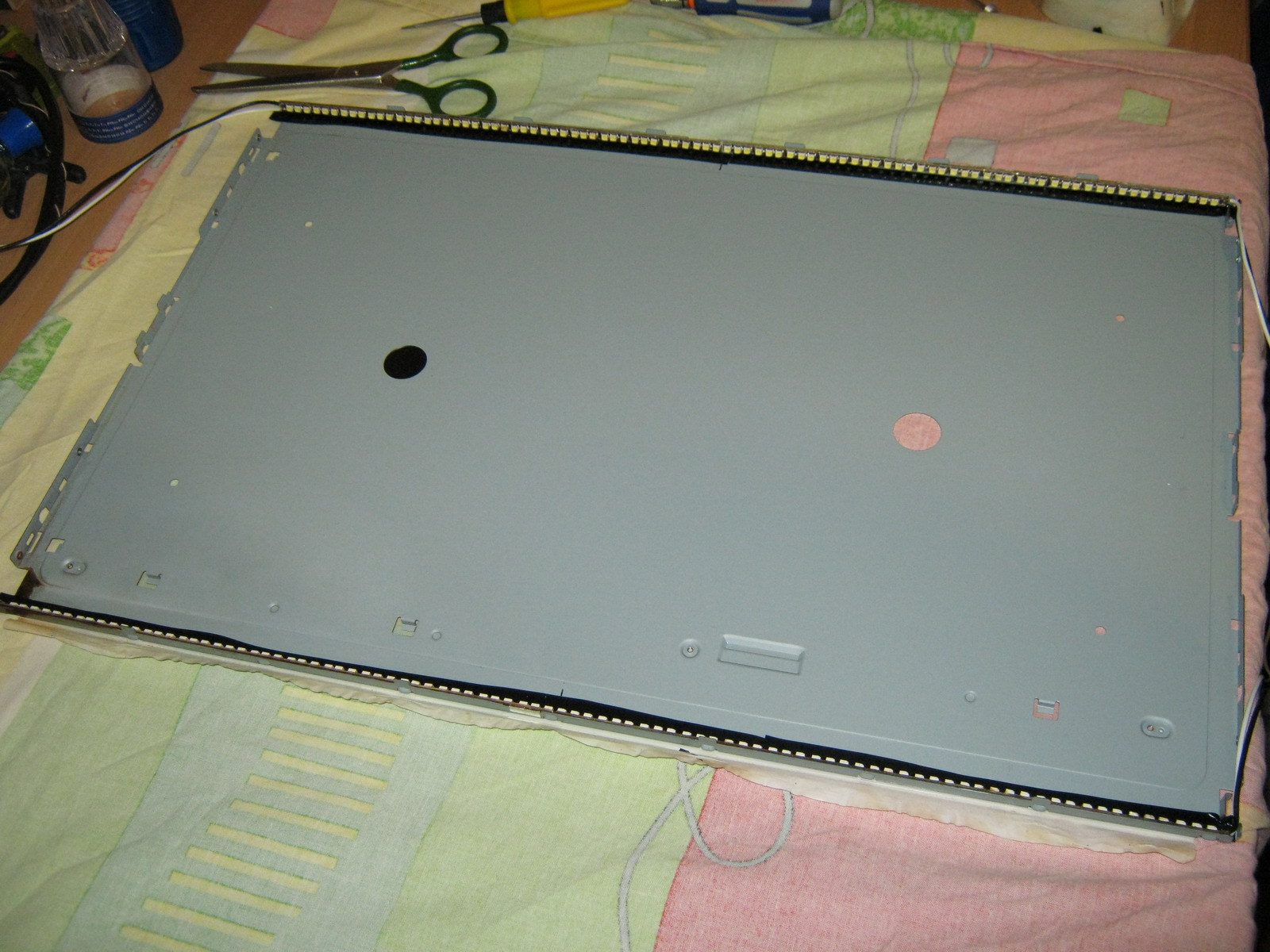
Installation of LED strip
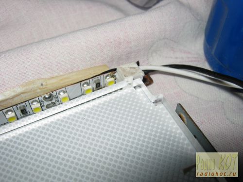
Since after cutting the tape by 1 mm, the power conductors were exposed at the ends of the tape, I pasted electrical tape (unfortunately, not blue but black) onto the body in the place where the tape will be glued. The tape is glued on top (it is good to warm the surface with a hairdryer, because the tape sticks much better to a warm surface): 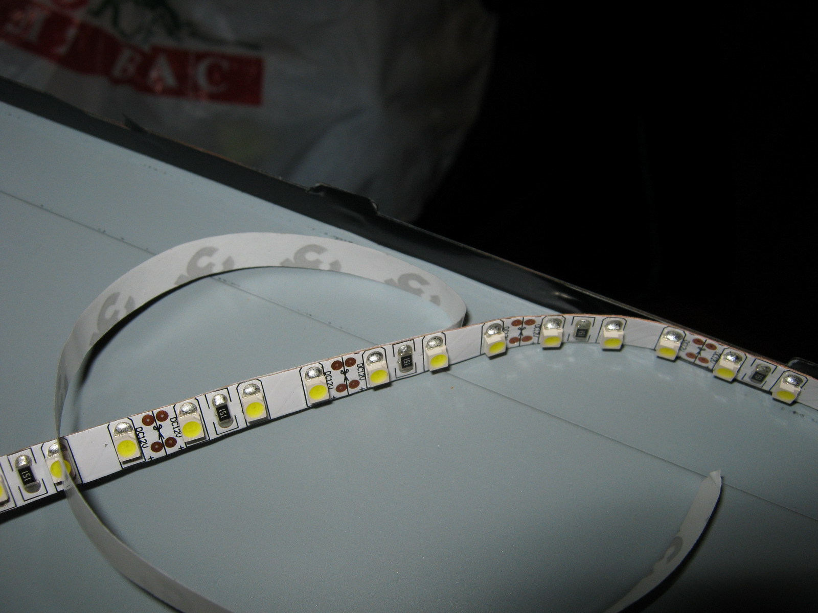
Next, the back film, plexiglass and light filters that lay on top of the plexiglass are mounted. Along the edges I supported the tape with pieces of eraser (so that the edges on the tape did not come off): 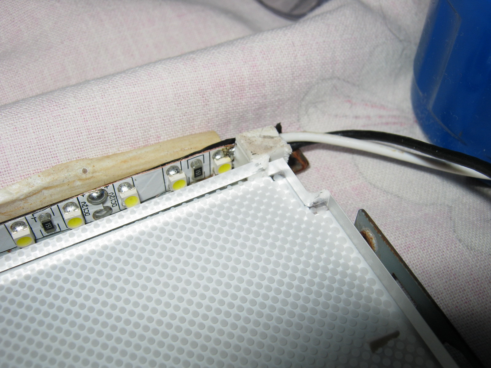
After that, the backlight unit is assembled in the reverse order, the matrix is installed in place, and the backlight wires are brought out.
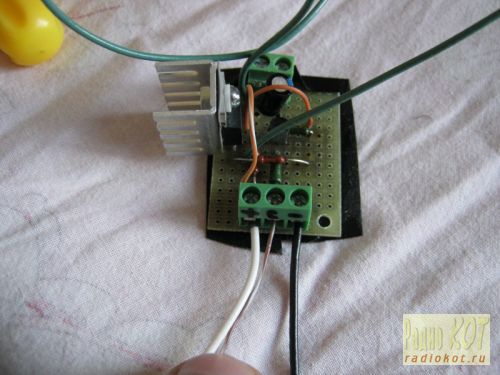
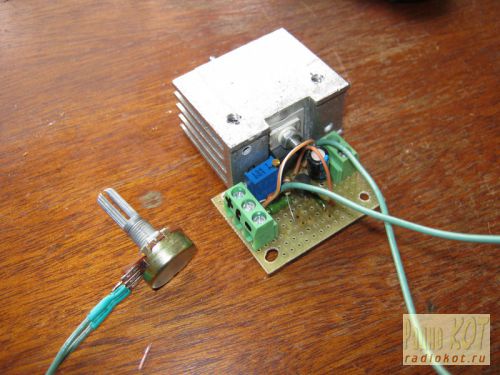
The circuit was assembled on a breadboard (due to simplicity, I decided not to wire the board), and was fastened with bolts through holes in the back wall of the metal monitor case: 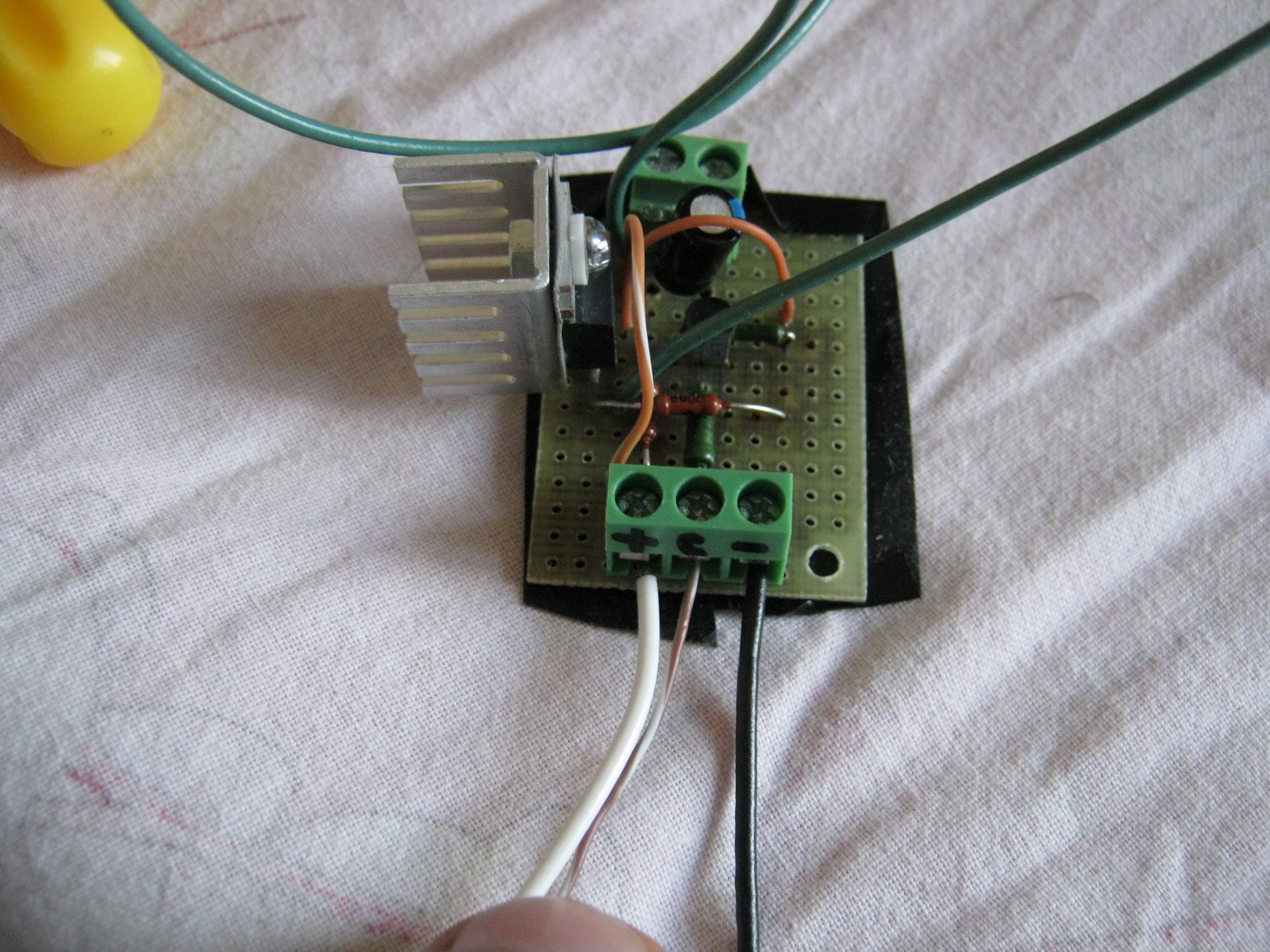
Power and control signal On were supplied from the power supply board: 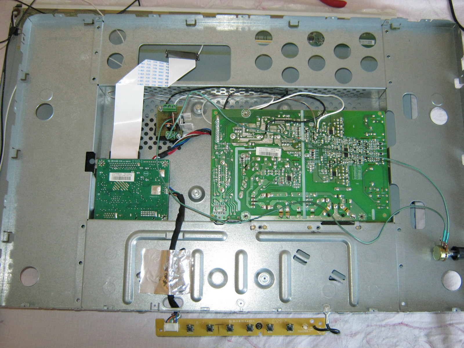
The estimated power allocated to the LM2941 is calculated using the formula:
Pd = (Vin-Vout)*Iout +Vin*Ignd
For my case, it is Pd = (13.6-13)*0.7 +13.6*0.006 = 0.5 Watt, so it was decided to make do with the smallest radiator for the LM2941 (placed through a dielectric pad since it is not isolated from the ground in the LM2941).
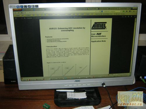
The final assembly showed that the design was fully functional: 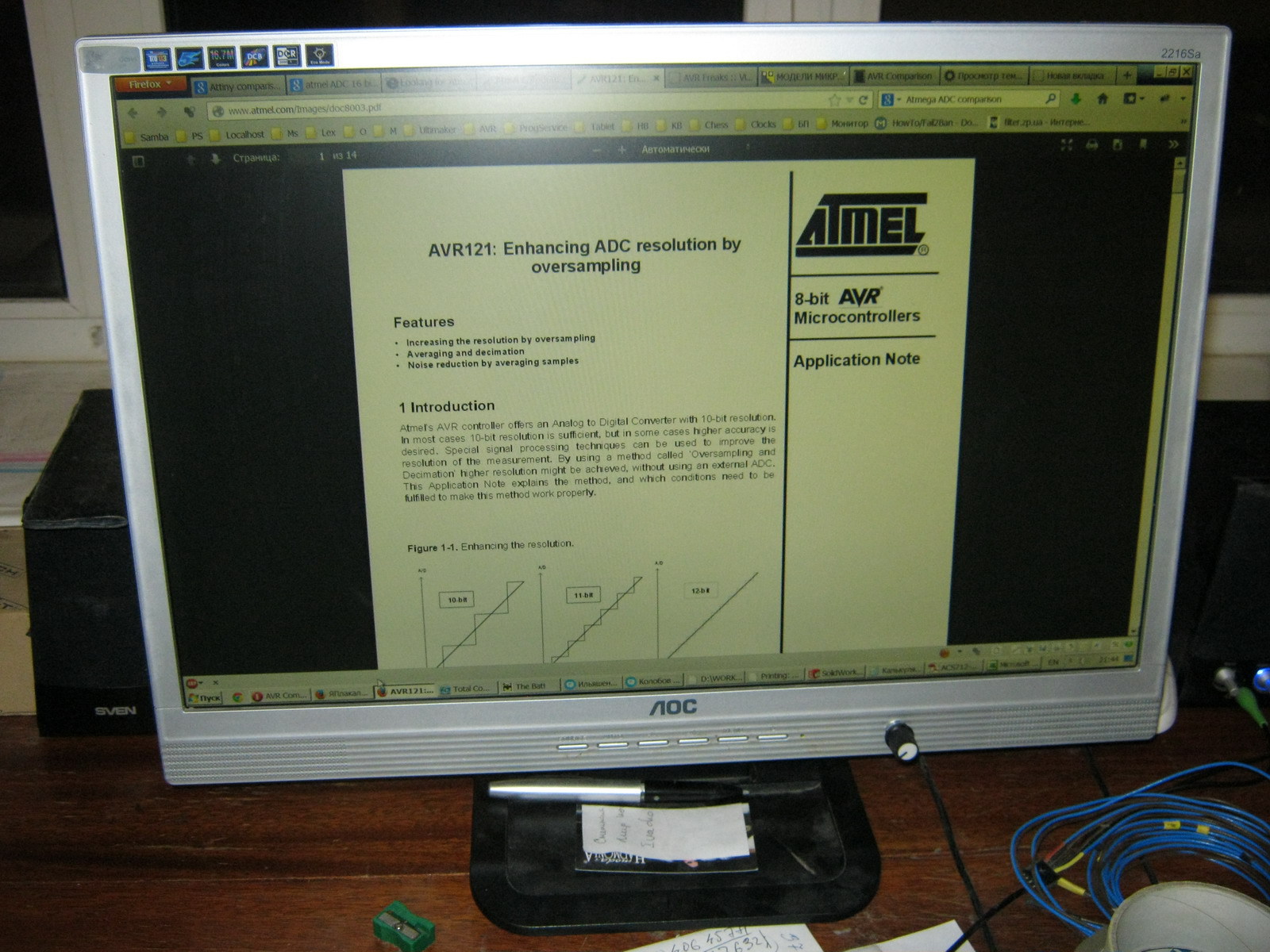
Among the advantages:
- Uses standard LED strip
- Simple control board
Disadvantages:
- Insufficient backlight brightness in bright daylight (the monitor is placed in front of a window)
- The LEDs in the strip are not spaced closely enough, so small cones of light from each individual LED are visible near the top and bottom edges of the monitor
- The white balance is a little off and goes slightly greenish (most likely this can be solved by adjusting the white balance of either the monitor itself or the video card)
Quite good, simple and a budget option backlight repair. It’s quite comfortable to watch movies or use the monitor as a kitchen TV, but it’s probably not suitable for everyday work.
Adjusting brightness using PWM
For those Habro residents who, unlike me, do not remember with nostalgia the analogue brightness and contrast control knobs on old CRT monitors, you can make control from the standard PWM generated by the monitor control board without moving any additional controls outside (without drilling the monitor body). To do this, it is enough to assemble an AND-NOT circuit on two transistors at the On/Off input of the regulator and remove the brightness control at the output (set the output voltage to constant 12-13V). Modified scheme: 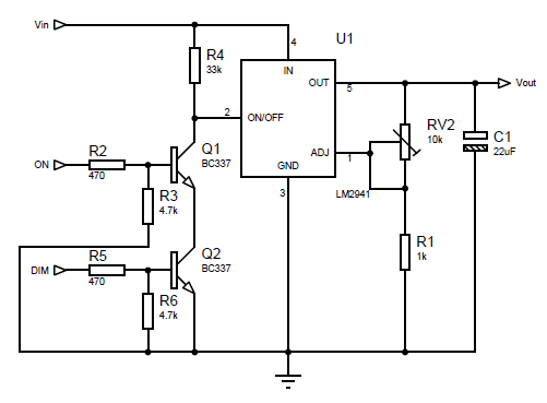
Trimmer resistor resistance
More dense LED backlight
To solve the problem of insufficient brightness (and at the same time uniformity) of the backlight, it was decided to install more LEDs and more often. Since it turned out that buying LEDs individually is more expensive than buying 1.5 meters of strip and desoldering them from there, a more economical option was chosen (desoldering LEDs from the strip).
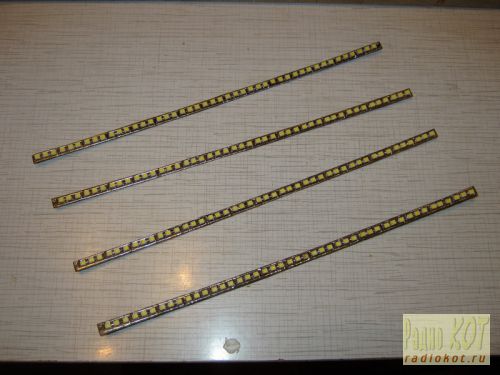
The 3528 LEDs themselves are placed on 4 strips 6 mm wide and 238 mm long, 3 LEDs in series in 15 parallel assemblies on each of the 4 strips (the layout of the boards for the LEDs is included). After soldering the LEDs and wires, the following is obtained: 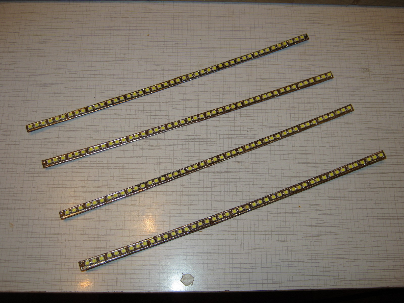
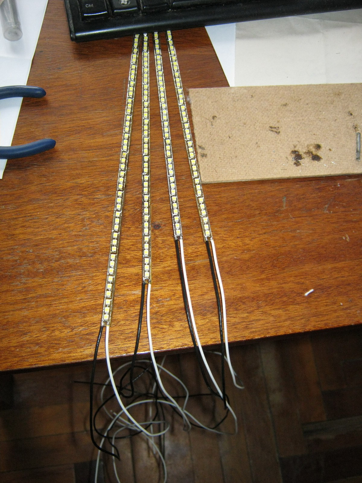
The strips are laid in twos at the top and bottom with wires to the edge of the monitor at the joint in the center: 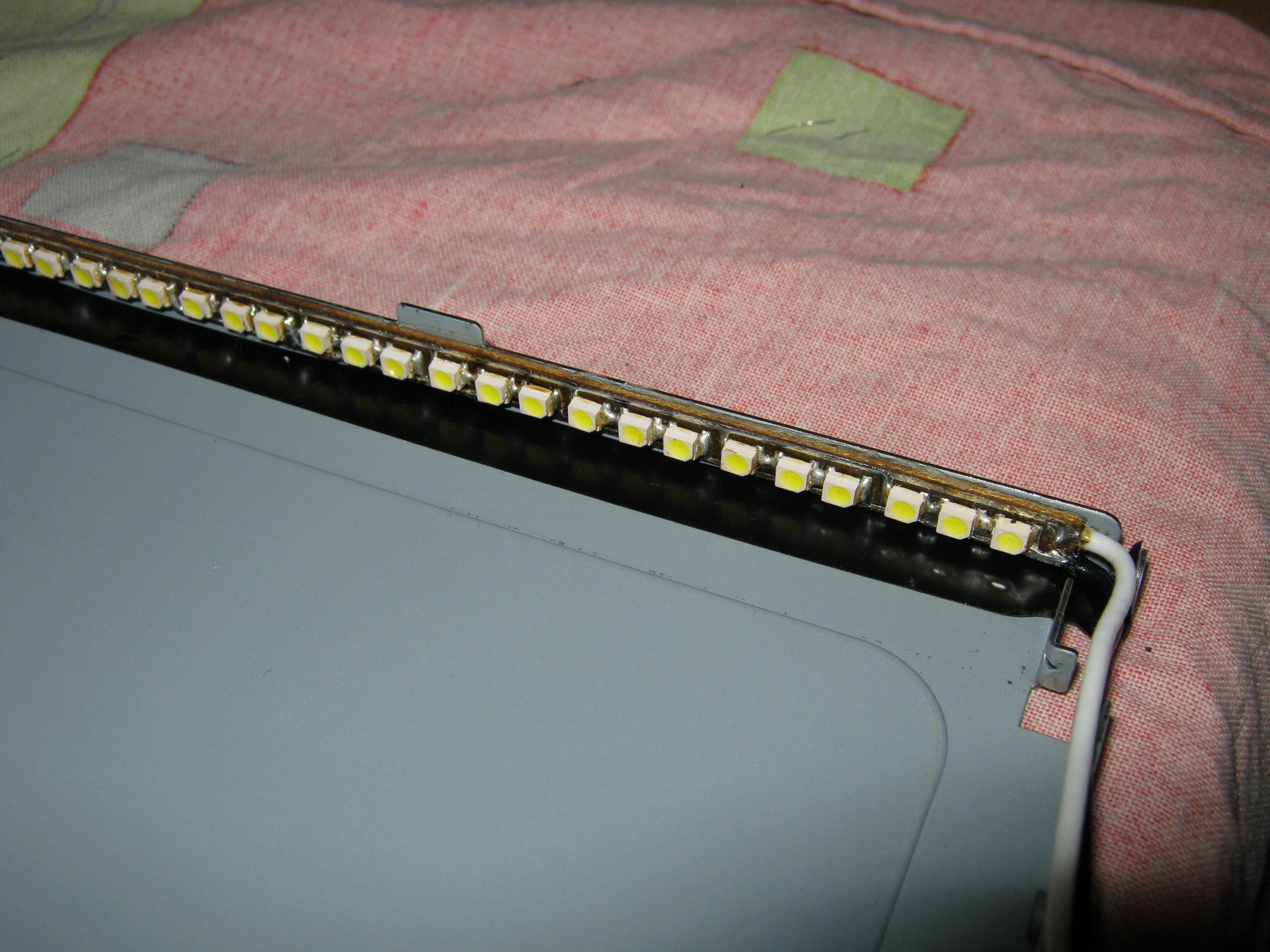
The nominal voltage on the LEDs is 3.5V (range from 3.2 to 3.8 V), so an assembly of 3 LEDs in series should be powered with a voltage of about 10.5V. So the controller parameters need to be recalculated: 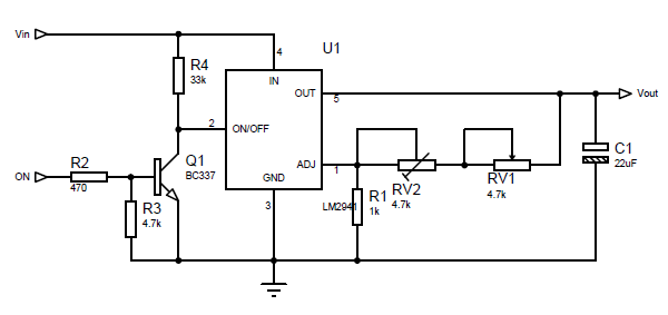
The maximum voltage we need for the tape is 10.5V. Those. maximum value R2 = 1000*(10.5/1.275-1) = 7.23 kOhm. The minimum voltage at which the LED assembly still glows at least somehow is about 4.5 volts, i.e. minimum value R2 = 1000*(4.5/1.275-1) = 2.53 kOhm. Our R2 consists of a variable resistor RV1 and a multi-turn trimming resistor RV2. Resistance RV1 is 7.23 kOhm - 2.53 kOhm = 4.7 kOhm, and RV2 is set to approximately 7.23-4.7 = 2.53 kOhm and adjusted to assembled circuit to obtain 10.5V at the output of LM2941 at maximum resistance RV1.
One and a half times more LEDs consume 1.2A of current (nominally), so the power dissipation on the LM2941 will be equal to Pd = (13.6-10.5)*1.2 +13.6*0.006 = 3.8 Watt, which already requires a more solid heatsink for heat removal: 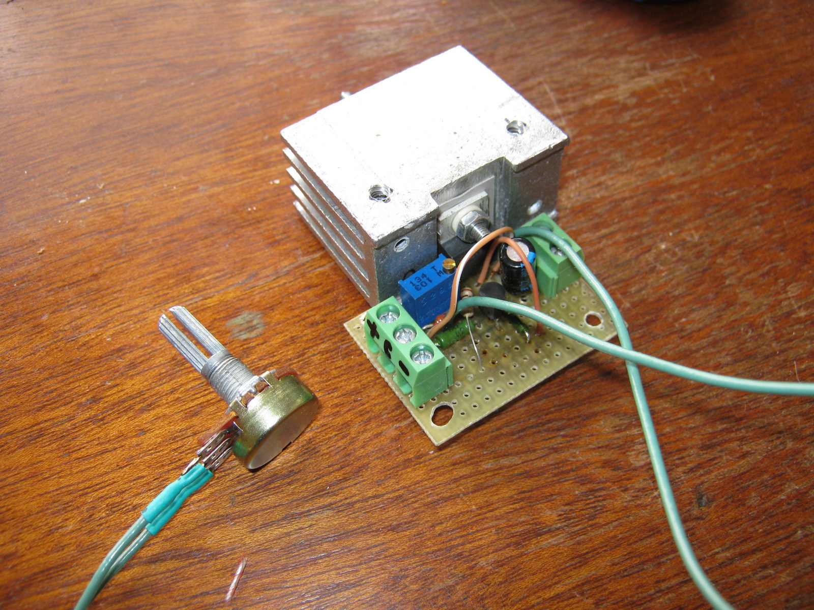
We collect, connect, we get much better: 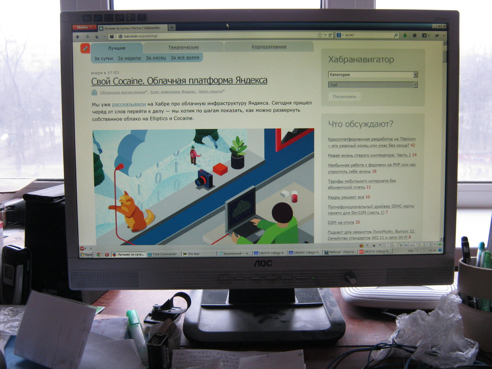
Advantages:
- Quite high brightness (possibly comparable, and perhaps even superior to the brightness of the old CCTL backlight)
- The absence of light cones at the edges of the monitor from individual LEDs (LEDs are located quite often and the backlight is uniform)
- Still a simple and cheap control board
Flaws:
- The issue with the white balance, which goes into greenish tones, has not been resolved
- LM2941, although with a large heatsink, gets hot and heats everything inside the case
Control board based on step-down regulator
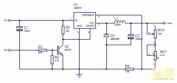
To eliminate the heating problem, it was decided to assemble a brightness controller based on a Step-down voltage regulator (in my case, an LM2576 with a current of up to 3A was chosen). It also has an inverted On/Off control input, so for matching there is the same inverter on one transistor: ![]()
Coil L1 affects the efficiency of the converter and should be 100-220 µH for a load current of about 1.2-3A. The output voltage is calculated using the formula:
Vout=Vref*(1+R2/R1)
where Vref = 1.23V. For a given R1, you can obtain R2 using the formula:
R2=R1*(Vout/Vref-1)
In calculations, R1 is equivalent to R4 in the circuit, and R2 is equivalent to RV1+RV2 in the circuit. In our case, to adjust the voltage in the range from 7.25V to 10.5V, we take R4 = 1.8 kOhm, variable resistor RV1 = 4.7 kOhm and trimming resistor RV2 at 10 kOhm with an initial approximation of 8.8 kOhm (after assembling the circuit, it is best to set its exact value by measuring the voltage at the output of LM2576 at maximum resistance RV1).
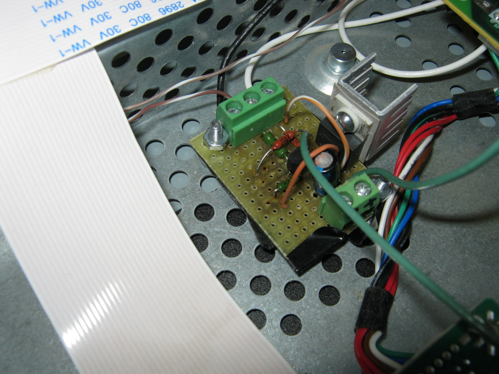
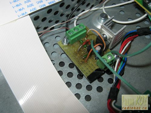
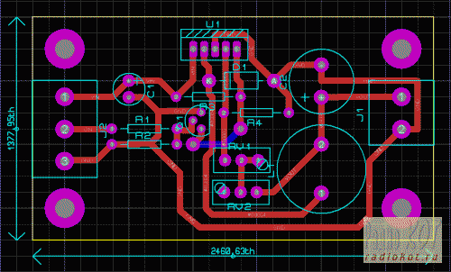
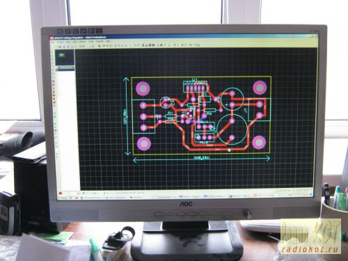
I decided to make a board for this regulator (the dimensions did not matter, since there is enough space in the monitor to mount even a large board): 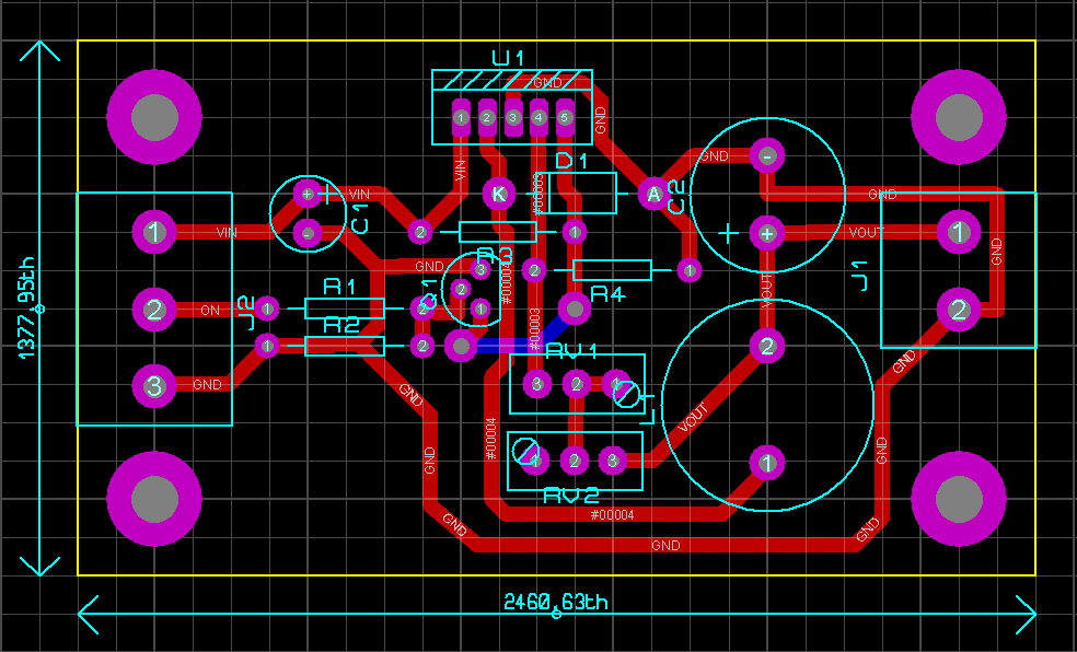
Control board assembly: 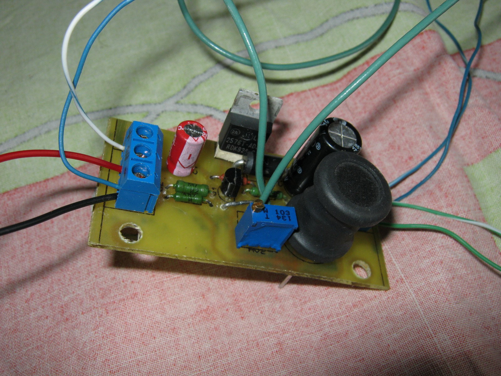
After installation in the monitor: ![]()
Everyone is here: 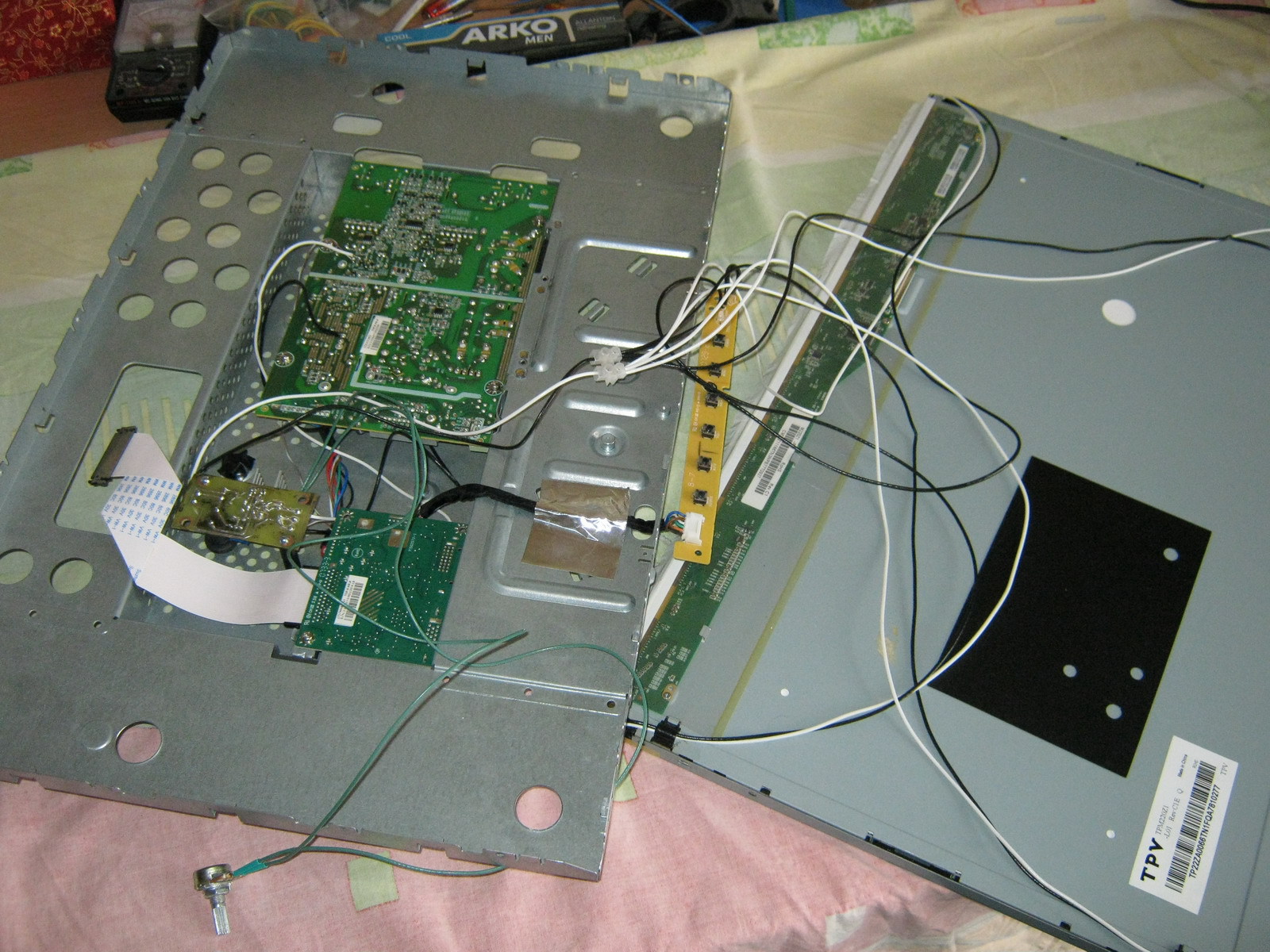
After assembly everything seems to work: 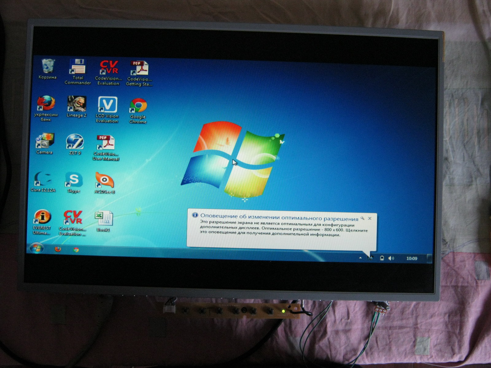
Final option: 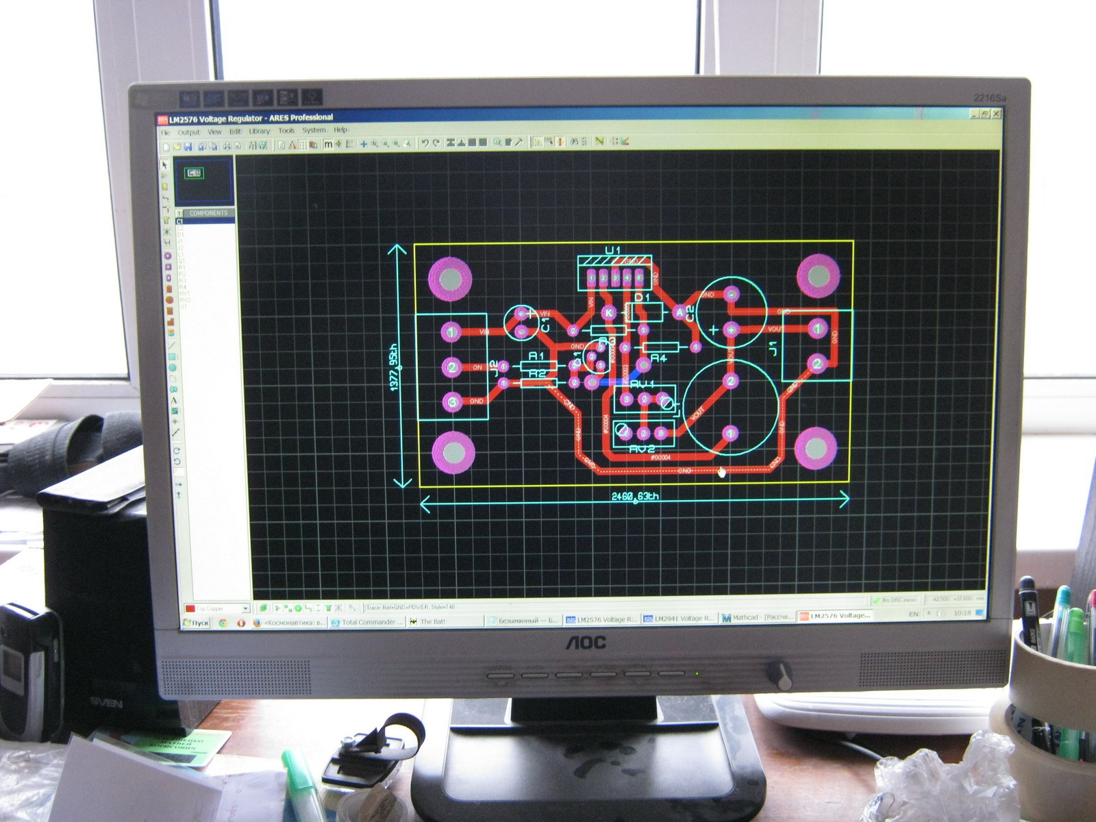
Advantages:
- Sufficient brightness
- Step-down regulator does not heat up and does not warm up the monitor
- There is no PWM, which means nothing blinks at any frequency
- Analogue (manual) brightness control
- No restrictions on minimum brightness (for those who like to work at night)
Flaws:
- The white balance is slightly shifted towards green tones (but not much)
- At low brightness (very low), unevenness in the glow of LEDs of different assemblies is visible due to the spread of parameters
Improvement options:
- White balance is adjustable both in the monitor settings and in the settings of almost any video card
- You can try installing other LEDs that will not noticeably disrupt the white balance
- To eliminate the uneven glow of LEDs at low brightness, you can use: a) PWM (adjust the brightness using PWM by always supplying the rated voltage) or b) connect all the LEDs in series and power them with an adjustable current source (if you connect all 180 LEDs in series, you will need 630V and 20mA), then the same current should pass through all the LEDs, and each one will have its own voltage drop; the brightness is regulated by changing the current and not the voltage.
- If you want to make a PWM-based circuit for LM2576, you can use a NAND circuit at the On/Off input of this Step-down regulator (similar to the above circuit for LM2941), but it is better to put a dimmer in the gap of the negative wire of the LEDs via a logic-level mosfet
Time passes unnoticed and seemingly recently purchased equipment is already breaking down. So, having worked their 10,000 hours, the lamps of my monitor (AOC 2216Sa) gave up their life. At first, the backlight did not turn on the first time (after turning on the monitor, the backlight turned off after a few seconds), which was solved by turning the monitor on/off again; over time, the monitor had to be turned off/off 3 times, then 5, then 10, and at some point it could not turn on the backlight, regardless of the number of attempts to turn it on. The lamps brought to the light of day turned out to have blackened edges and were legally thrown into scrap. An attempt to install replacement lamps (new lamps of the appropriate size were purchased) was unsuccessful (the monitor was able to turn on the backlight several times, but quickly went into on-off mode again) and finding out the reasons for what the problem could be in the electronics of the monitor led me to the idea that it will be easier to assemble your own monitor backlight using LEDs than to repair the existing inverter circuit for CCFL lamps, especially since there have already been articles on the Internet showing the fundamental possibility of such a replacement.
Disassembling the monitor
Many articles have already been written on the topic of disassembling a monitor; all monitors are very similar to each other, so in brief:
1. Unscrew the monitor delivery mount and the only bolt at the bottom that holds the back wall of the case
2. At the bottom of the case there are two grooves between the front and back of the case, insert a flat-head screwdriver into one of them and begin to remove the cover from the latches along the entire perimeter of the monitor (simply turning the screwdriver carefully around its axis and thereby lifting the case cover). There is no need to exert excessive effort, but it is difficult to remove the case from the latches only the first time (during the repair I opened it many times, so the latches became much easier to remove over time).
3. We have a view of the installation of the internal metal frame in the front part of the housing:
We take out the board with the buttons from the latches, take out (in my case) the speaker connector and, bending the two tabs at the bottom, take out the inner metal case.
4. On the left you can see 4 wires connecting the backlight lamps. We take them out by squeezing them slightly, because... To prevent it from falling out, the connector is made in the form of a small clothespin. We also remove the wide cable going to the matrix (at the top of the monitor), squeezing its connector on the sides (since the connector has side latches, although this is not obvious at first glance at the connector):
5. Now you need to disassemble the “sandwich” containing the matrix itself and the backlight:
There are latches along the perimeter that can be opened by lightly prying with the same flat screwdriver. First, the metal frame holding the matrix is removed, after which you can unscrew three small bolts (a regular Phillips screwdriver will not work due to their miniature size, you will need a particularly small one) holding the matrix control board and the matrix can be removed (it is best to place the monitor on a hard surface, such as a table covered with the fabric facing down, unscrew the control board, place it on the table, unfolding it through the end of the monitor, and simply lift the backlit case, lifting it vertically up, and the matrix will remain lying on the table. It can be covered with something so as not to gather dust, and assembled exactly the opposite way. order - i.e. cover the matrix lying on the table with the assembled case with backlight, wrap the cable through the end to the control board and, screwing the control board, carefully lift the assembled unit).
The matrix is obtained separately:
And the backlit block:
The backlit block is disassembled in the same way, only instead of a metal frame, the backlight is held by a plastic frame, which simultaneously positions the plexiglass used to diffuse the backlight light. Most of the latches are on the sides and are similar to those that held the metal frame of the matrix (they open by prying them off with a flat-head screwdriver), but on the sides there are several latches that open “inward” (you need to press on them with a screwdriver so that the latches go inside the case).
At first I remembered the position of all the parts to be removed, but then it turned out that it would not be possible to assemble them “wrongly” and even if the parts look absolutely symmetrical, the distances between the latches on different sides of the metal frame and the locking protrusions on the sides of the plastic frame holding the backlight will not allow them to be assembled “wrongly” ".
That's all - we disassembled the monitor.
LED strip backlighting
At first, it was decided to make the backlight from an LED strip with white LEDs 3528 - 120 LEDs per meter. The first thing that turned out to be is that the width of the tape is 9 mm, and the width of the backlight lamps (and the seat for the tape) is 7 mm (in fact, there are backlight lamps of two standards - 9 mm and 7 mm, but in my case they were 7 mm). Therefore, after examining the tape, it was decided to cut 1 mm from each edge of the tape, because this did not affect the conductive paths on the front part of the tape (and on the back, along the entire tape, there are two wide power cores, which will not lose their properties due to a decrease of 1 mm over a backlight length of 475 mm, since the current will be small). No sooner said than done:
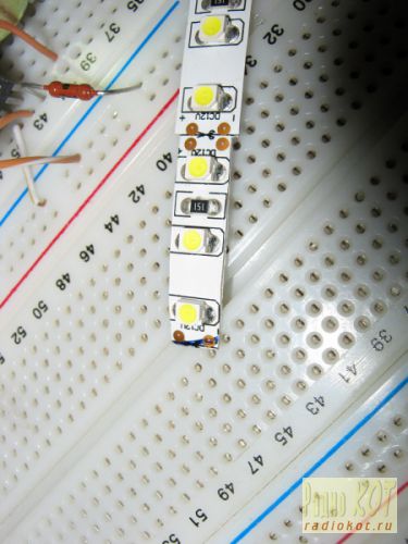
In the same way, the LED strip is carefully trimmed along its entire length (the photo shows an example of what happened before and what happened after trimming).
We will need two strips of 475 mm tape (19 segments of 3 LEDs per strip).
I wanted the monitor backlight to work the same way as the standard one (that is, it was turned on and off by the monitor controller), but I wanted to adjust the brightness “manually”, as on old CRT monitors, because This is a frequently used function, and I got tired of navigating through on-screen menus pressing several keys every time (on my monitor, the right-left keys do not adjust the monitor modes, but the volume of the built-in speakers, so the modes had to be changed through the menu every time). To do this, I found a manual for my monitor on the Internet (for those who need it, it is attached at the end of the article) and on the page with the Power Board, according to the diagram, +12V, On, Dim and GND were found that are of interest to us.
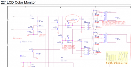
On - signal from the control board to turn on the backlight (+5V)
Dim - PWM backlight brightness control
12V turned out to be far from 12, but somewhere around 16V without a backlight load and somewhere around 13.67V with a load
It was also decided not to make any PWM adjustments to the backlight brightness, but to power the backlight with direct current (at the same time, the issue is resolved that on some monitors the PWM backlight operates at a not very high frequency and for some this makes their eyes a little more tired). In my monitor, the “native” PWM frequency was 240 Hz.
Further on the board we found contacts to which the On signal is sent (marked in red) and +12V to the inverter unit (the jumper that must be pulled out to de-energize the inverter unit is marked in green). (photo can be enlarged to see notes):
The basis of the control circuit was to take the linear regulator LM2941 mainly because, with a current of up to 1A, it had a separate On/Off control pin, which was supposed to be used to control the on/off of the backlight with the On signal from the monitor control board. True, in LM2941 this signal is inverted (i.e., there is voltage at the output when the On/Off input is zero potential), so we had to assemble an inverter on one transistor to match the direct On signal from the control board and the inverted input of LM2941. The scheme does not contain any other excesses:
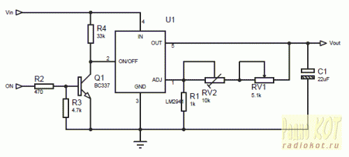
The output voltage for LM2941 is calculated using the formula:
Vout = Vref * (R1+R2)/R1
where Vref = 1.275V, R1 in the formula corresponds to R1 in the diagram, and R2 in the formula corresponds to a pair of resistors RV1+RV2 in the diagram (two resistors were introduced for smoother brightness adjustment and reducing the range of voltages regulated by the variable resistor RV1).
I took 1kOhm as R1, and the selection of R2 is carried out according to the formula:
R2=R1*(Vout/Vref-1)
The maximum voltage we need for the tape is 13V (I took a little more than the nominal 12V so as not to lose brightness, and the tape will survive such a slight overvoltage). Those. maximum value R2 = 1000*(13/1.275-1) = 9.91 kOhm. The minimum voltage at which the tape still glows at least somehow is about 7 volts, i.e. minimum value R2 = 1000*(7/1.275-1) = 4.49 kOhm. Our R2 consists of a variable resistor RV1 and a multi-turn trimming resistor RV2. The resistance of RV1 is 9.91 kOhm - 4.49 kOhm = 5.42 kOhm (we select the closest value of RV1 - 5.1 kOhm), and RV2 is set to approximately 9.91-5.1 = 4.81 kOhm (in fact, it is best to first assemble the circuit, set the maximum resistance of RV1 and measure the voltage at At the output of LM2941, set the resistance RV2 so that the output has the required maximum voltage (in our case, about 13V).
Installation of LED strip
Since after cutting the tape by 1 mm, the power conductors were exposed at the ends of the tape, I pasted electrical tape (unfortunately, not blue but black) onto the body in the place where the tape will be glued. The tape is glued on top (it is good to warm the surface with a hairdryer, because the tape sticks much better to a warm surface):
After that, the backlight unit is assembled in the reverse order, the matrix is installed in place, and the backlight wires are brought out.
The circuit was assembled on a breadboard (due to simplicity, I decided not to wire the board), and was attached to bolts through holes in the back wall of the metal monitor case:
Power and control signal On were supplied from the power supply board:
The estimated power allocated to the LM2941 is calculated using the formula:
Pd = (Vin-Vout)*Iout +Vin*Ignd
For my case, it is Pd = (13.6-13)*0.7 +13.6*0.006 = 0.5 Watt, so it was decided to make do with the smallest radiator for the LM2941 (placed through a dielectric pad since it is not isolated from the ground in the LM2941).
The final assembly showed that the design was fully functional:
Among the advantages:
- Uses standard LED strip
- Simple control board
Disadvantages:
- Insufficient backlight brightness in bright daylight (the monitor is placed in front of a window)
- The LEDs in the strip are not spaced closely enough, so small cones of light from each individual LED are visible near the top and bottom edges of the monitor
- The white balance is a little off and goes slightly greenish (most likely solved by adjusting the white balance of either the monitor itself or the video card)
Quite a good, simple and budget option for repairing the backlight. It’s quite comfortable to watch movies or use the monitor as a kitchen TV, but it’s probably not suitable for everyday work.
More dense LED backlight
To solve the problem of insufficient brightness (and at the same time uniformity) of the backlight, it was decided to install more LEDs and more often. Since it turned out that buying LEDs individually is more expensive than buying 1.5 meters of strip and desoldering them from there, a more economical option was chosen (desoldering LEDs from the strip).
The 3528 LEDs themselves are placed on 4 strips 6 mm wide and 238 mm long, 3 LEDs in series in 15 parallel assemblies on each of the 4 strips (the layout of the boards for the LEDs is included). After soldering the LEDs and wires, the following is obtained:
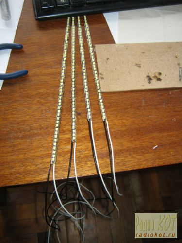
The strips are laid in twos at the top and bottom with wires to the edge of the monitor at the joint in the center:
The nominal voltage on the LEDs is 3.5V (range from 3.2 to 3.8 V), so an assembly of 3 LEDs in series should be powered with a voltage of about 10.5V. So the controller parameters need to be recalculated:
The maximum voltage we need for the tape is 10.5V. Those. maximum value R2 = 1000*(10.5/1.275-1) = 7.23 kOhm. The minimum voltage at which the LED assembly still glows at least somehow is about 4.5 volts, i.e. minimum value R2 = 1000*(4.5/1.275-1) = 2.53 kOhm. Our R2 consists of a variable resistor RV1 and a multi-turn trimming resistor RV2. The resistance of RV1 is 7.23 kOhm - 2.53 kOhm = 4.7 kOhm, and RV2 is set to approximately 7.23-4.7 = 2.53 kOhm and adjusted in the assembled circuit to obtain 10.5 V at the output of LM2941 at the maximum resistance of RV1.
One and a half times more LEDs consume 1.2A current (nominally), so the dissipation capacity on the LM2941 will be equal to Pd = (13.6-10.5)*1.2 +13.6*0.006 = 3.8 Watt, which already requires a more solid heatsink for heat removal:
We collect, connect, we get much better:
Advantages:
- Quite high brightness (possibly comparable, and perhaps even superior to the brightness of the old CCTL backlight)
- The absence of light cones at the edges of the monitor from individual LEDs (LEDs are located quite often and the backlight is uniform)
- Still a simple and cheap control board
Flaws:
- The issue with the white balance, which goes into greenish tones, has not been resolved
- LM2941, although with a large heatsink, gets hot and heats everything inside the case
Control board based on step-down regulator
To eliminate the problem of regeno heating, it was necessary to assemble a brightness controller based on a Step-down voltage regulator (in my case, an LM2576 with a current of up to 3A was chosen). It also has an inverted On/Off control input, so for matching there is the same inverter on one transistor:
Coil L1 affects the efficiency of the converter and should be 100-220 µH for a load current of about 1.2-3A. The output voltage is calculated using the formula:
Vout=Vref*(1+R2/R1)
where Vref = 1.23V. Given R1, R2 can be obtained using the formula:
R2=R1*(Vout/Vref-1)
In calculations, R1 is equivalent to R4 in the circuit, and R2 is equivalent to RV1+RV2 in the circuit. In our case, to adjust the voltage in the range from 7.25V to 10.5V, we take R4 = 1.8 kOhm, variable resistor RV1 = 4.7 kOhm and trimming resistor RV2 at 10 kOhm with an initial approximation of 8.8 kOhm (after assembling the circuit, it is best to set its exact value by measuring the voltage at the output of LM2576 at maximum resistance RV1).
I decided to make a board for this regulator (the dimensions didn’t matter, because the monitor has enough space to mount even a large board):
Control board assembly:
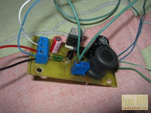
After installation in the monitor:
Everyone is here:
After assembly everything seems to work:
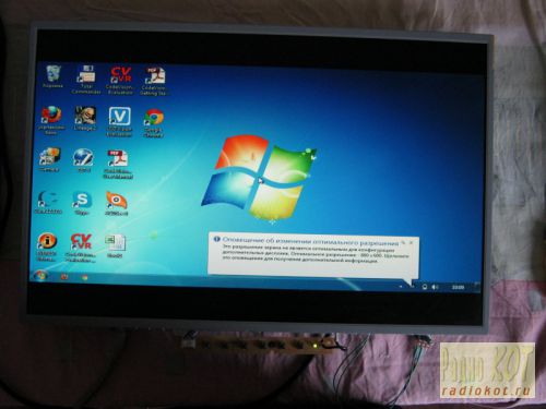
Final option:
Advantages:
- Sufficient brightness
- Step-down regulator does not heat up and does not warm up the monitor
- There is no PWM, which means nothing blinks at any frequency
- Analogue (manual) brightness control
- No restrictions on minimum brightness (for those who like to work at night)
Flaws:
- The white balance is slightly shifted towards green tones (but not much)
- At low brightness (very low), unevenness in the glow of LEDs of different assemblies is visible due to the spread of parameters
Improvement options:
- White balance is adjustable both in the monitor settings and in the settings of almost any video card
- You can try installing other LEDs that will not noticeably disrupt the white balance
- To eliminate the uneven glow of LEDs at low brightness, you can use: a) PWM (adjust the brightness using PWM by always supplying the rated voltage) or b) connect all the LEDs in series and power them with an adjustable current source (if you connect all 180 LEDs in series, you will need 630V and 20mA), then the same current should pass through all the LEDs, and each one will have its own voltage drop; the brightness is regulated by changing the current and not the voltage.
In the attached files:
- AOC-2216SA.rar - Service Manual for the AOC2216Sa monitor (divided into two parts because it exceeds the size limit for downloading one file)
Liquid crystal displays (LCDs) are passive information display devices. In order for the formed image to be perceived by the human eye, it must be illuminated, in the simplest case - with natural external light. In case of insufficient natural light or its absence for display can be used artificial source Sveta.
Most modern LCDs operate in one of three display modes: total reflection mode, in which external light is reflected from a reflector located behind the display (Fig. 1a); in the semi-reflection mode, in which the reflector reflects external light, but is capable of transmitting light from a light source located behind it (Fig. 1, b); in the backlight mode, in which there is no reflector reflecting external light and a special light source is used to illuminate the image (Fig. 1, c).
Rice. 1. LCD display modes
A technique that uses a special light source is called “backlight”. To implement backlighting, several technologies are used, which will be discussed below.
Electroluminescent (EL) backlight
Electroluminescent illumination provides uniform illumination and is made in a thin and light design (Fig. 2).

Rice. 2. Electroluminescent backlight design
This backlight produces a variety of colors, including white, which is most often used in LCDs. Consumption with electroluminescent illumination is relatively low, but its organization requires an alternating voltage source of 80...100 V with a frequency of about 400 Hz (typical value). DC/DC converters that transform voltage are used as such a source direct current 5, 12 or 24 V AC voltage required size. This is the most energy-efficient type of backlight and is most often used in battery-powered devices. The lifespan of electroluminescent backlight (brightness reduced by half from the original) is about 3...5 thousand hours and depends on the set brightness (Fig. 3).
Rice. 3. Lifespan of EL backlight, dependence of lifespan on set brightness
Distinctive features of electroluminescent backlight:
- a flat light source with a maximum thickness of 1.3 mm (1.5 mm including leads) provides uniform illumination of a large area;
- wide range of AC supply voltages (maximum value 150 V) with a frequency of 60…1000 Hz. If boost converters are available, it can be powered by a single battery with a voltage of 1.5 V;
- glow color: green-blue, yellow-green and white;
- performance characteristics of typical power modules: output voltage 110 V with a frequency of 400 Hz; load current 8 mA (at Ta = 20 °C and relative humidity 60%);
- operating temperature range - from 0 to 50 °C;
- storage temperature range from -20 to 60 °C.
Light-emitting diode (LED) backlight
LED backlighting is characterized by the longest service life - at least 50 thousand hours - and greater brightness than EL backlighting. The backlight is provided by solid state devices and can therefore be operated directly from a 5V voltage source without the use of converters. However, to limit the current through the LED, current limiting resistors must be installed. A chain of LEDs is located along the side surfaces of the display or in the form of a matrix under the diffuser (scatterer) and provides bright, uniform illumination (Fig. 4, a, b).
Rice. 4. Designs of matrix and side LED lighting
Side illumination is used in modules with the number of characters in a row up to 20. When the number of characters is over 20, a darker area is formed in the center of the LCD than at the edges. To eliminate this drawback, special measures are used, for example, additional lighting from above.
Matrix LED backlighting provides brighter, more uniform light. When designing such lighting, consumption is a determining factor. It is not recommended for use in battery-powered devices that require the backlight to be on at all times.
LED backlights operate at a supply voltage of 4.2 V (typical). Backlight consumption is determined by the number of LEDs turned on, and therefore, as the display size increases, consumption increases, ranging from 30 to 200 mA or more.
The color of LED backlight can be different, including white, but yellow-green backlight is most often used. Its light emission is higher than that of EL backlight. It is possible to control the brightness of the light using a potentiometer or PWM controller.
Taking into account the cost of converters used with EL, the use of LED backlighting is more economical. The thickness of a module with LED backlight is 2–4 mm thicker than that of a module with EL backlight or without backlight.
Distinctive features of LED backlight:
- low supply voltage, no need to use special converters;
- long life cycle - on average over 100 thousand hours;
- possibility of illumination in red, green, orange and white colors or multi-color illumination (switchable);
- side or matrix lighting;
- typical supply voltage - 4.2 V; consumption 30 to - 200 mA and above; brightness - 250 cd/m;
- no noise generation.
Cold cathode fluorescent lamp (CCFL) backlighting
CCFL backlighting is characterized by relatively low consumption and very bright White light. Two technologies are used: direct and side illumination (Figure 5, a, b).
Rice. 5. Designs for direct and side illumination with cold cathode fluorescent lamps
In both cases, the light source is cold cathode fluorescent lamps (local light spot sources), the light from which is distributed over the entire screen area by diffusers and light guides. Side lighting makes it possible to implement modules of small thickness and with lower consumption. CCFL backlighting is used primarily in graphic LCDs, and the service life of CCFL backlighting is higher than that of EL backlighting - up to 10–15 thousand hours.
CCFL provides illumination of large surfaces, so it is used primarily in large flat panel displays. The great advantage of CCFL is the ability to produce paper-white color, which makes CCFL practically the only source of backlight for color displays. To operate fluorescent lamps, converters with an AC output voltage of 270 to 300 V are required.
Distinctive features of backlighting with cold cathode fluorescent lamps (CCFL):
In table Tables 1–3 show the characteristics of cold cathode fluorescent lamps.
Table 1. Maximum values
Table 2. Electrical characteristics
Table 3. Optical characteristics
In the table below. 4 provides comparative characteristics of the three main types of backlighting and their main areas of application.
Table 4.
| Backlight type | Use tion, depending on lighting conditions |
Consumption | Price | RFI generation | Brightness control | Notes |
| No | Not applicable in low light conditions | Best (does not consume by nature) | Least | Absent | Not used | |
| EL | Very good 30 mW | Average | Minor (at low frequencies) | Fixed brightness | Prefer Suitable for battery powered devices |
|
| LED | Can be used in all lighting conditions | Good 60 mW | Average | Absent | Widely adjustable | Most often used in small displays |
| CCFL | Not suitable for use in bright lighting conditions | Substantial 700 mW | The tallest | Sometimes (at high frequency) | Adjustable within a limited range | Most often used in large graphic displays |