How to check the backlight lamps of a Samsung monitor. How to repair or repair an LCD and LCD TV yourself if its inverter is broken. The main malfunctions of inverters in modern LCD and plasma TVs, as well as ways to eliminate them at home
The inverter in a TV is a device for starting and stable operation of fluorescent lamps for the backlight of an LCD panel. Ensures the constant glow of these light sources for a long time and effectively controls their brightness. It can be made in the form of one or two separate blocks (master/slave), and also located together with the power supply on a single board. If you do it yourself, you need to know the functions it performs.
Tasks of the television inverter:
- conversion of direct voltage 12 - 24 volts into high-voltage alternating voltage
- stabilization and adjustment of lamp current
- backlight brightness adjustment
- providing protection against overloads and short circuits
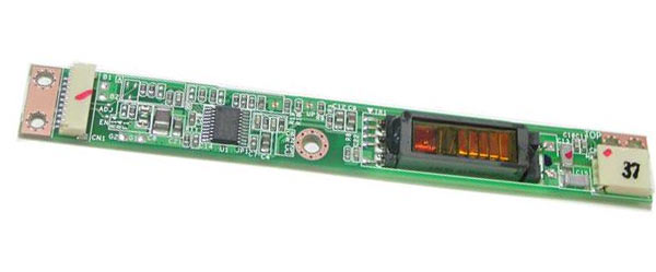
Electrical circuit of a simple inverter for 2 backlight lamps
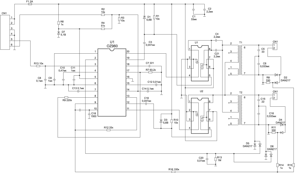
 The device is implemented on a PWM controller U1 (OZ960), two assemblies of field-effect transistor switches (u1, u2) and high-voltage transformers T1, T2. Connector CN1 supplies 12 volt power (F1), a power command (ON/OFF), and constant pressure(Dimm) to adjust brightness. The protection unit (D2, D4, D5, D6) analyzes the current or voltage at the output of the device and generates overload voltages and feedback(OS) supplied to PWM. If one of these voltages exceeds the threshold value, the oscillator at U1 is blocked, and the inverter will be in a protection state. The node is blocked when undervoltage power supply, when the supply voltage “drops” at the moment the load is turned on, when the converter is overloaded or a short circuit.
Characteristic signs of inverter malfunction
- Backlights do not turn on
- The backlights turn on a short time and turn off
- Unstable brightness and screen flickering
- The inverter periodically does not turn on after a long period of inactivity
- Uneven screen illumination with a 2-inverter circuit
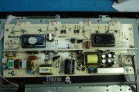
Features of inverter unit repair
 When diagnosing faults related to the correct operation of the inverter, you should first of all make sure that there is no ripple in the supply voltage and that it is stable. Pay attention to the passage of startup commands and backlight brightness control from the motherboard. Eliminate the influence of backlight lamps by using their equivalent in cases where the problem is not clear. Take advantage of the opportunity to remove protection from the inverter during repairs to determine the defective part. Do not forget about a careful visual inspection of the board and what every professional TV technician uses when repairing TVs at home - measuring voltage, resistance, capacitance using special instruments or a tester.
Sometimes, upon careful inspection of the board, you can see “burnt out” parts that need to be replaced. Very often field-effect transistor switches fail, but sometimes replacing them does not always lead to a positive result. The functionality of the unit may be restored for an indefinite period of time, and then the malfunction may occur again. You have eliminated the effect, but not the cause. Therefore, without knowing the intricacies of repairing these devices, you can lose a lot of time and effort to restore them. And, if you have doubts about the success of the matter, call a technician who has already repaired similar devices many times and knows all the “pitfalls and shoals” thanks to his accumulated experience and professional knowledge.
![]() High-voltage transformers are considered the weak link in the inverter units. Operation under high voltage conditions requires special assembly quality of these components and places high demands on the insulation properties. In addition, it should be said that transformers can become noticeably heated during the operation of the backlight. Defects such as a break or inter-turn short circuit of the windings of these parts are commonplace. Diagnostics of these elements can be complicated by the fact that a short circuit or break can only be observed in operating mode, and “diagnosis” of them in a de-energized state will not reveal problems with them. Here, swapping the dubious and serviceable transformer and further analyzing the situation can come to the rescue.
High-voltage transformers are considered the weak link in the inverter units. Operation under high voltage conditions requires special assembly quality of these components and places high demands on the insulation properties. In addition, it should be said that transformers can become noticeably heated during the operation of the backlight. Defects such as a break or inter-turn short circuit of the windings of these parts are commonplace. Diagnostics of these elements can be complicated by the fact that a short circuit or break can only be observed in operating mode, and “diagnosis” of them in a de-energized state will not reveal problems with them. Here, swapping the dubious and serviceable transformer and further analyzing the situation can come to the rescue.
 Different TVs use inverters with different numbers of transformers. In small-sized devices, the inverter can contain 2 - 4 transformers; in large-diagonal TVs, especially of previous years of production, there were up to 20 similar products. Naturally, a large number of them reduces the reliability of the circuit as a whole, so in modern models their use is minimized due to innovative technical solutions.
A sign of an inverter malfunction in most cases is the absence of an image on the TV screen when there is sound. However, situations are possible when the TV, after trying to turn on, goes back into standby mode or starts flashing the LEDs on the front panel, and in this case no sound appears. The nature of the defect is different, and the source may still be the same inverter unit. Some TV models contain a feedback signal from the inverter to the motherboard processor, indicating malfunctions in its operation. Without receiving confirmation from the inverter that everything is fine with it, the processor changes the TV’s operating mode to standby or displays error messages through LED indicators. For some manufacturers, after a certain number of unsuccessful starts, the system may stop sending a command to turn on the backlight until errors are reset or the memory is cleared.
 The inverter is a complex electronic device, which can cause some difficulties when repairing it yourself. These blocks for TVs with diagonals from 26 inches and above are “tied” to a specific LCD panel and, according to manufacturers, are a single device (together with the T-con block). It is very rare to find electronic circuits for these products, and never for a matrix controller. Therefore, even a professional, when diagnosing this equipment, has to recall the experience of repairing similar devices, be guided by the general principles of their circuit design solutions and use the database of datasheets for backlight driver microcircuits and key transistors. If you decide to repair the inverter yourself, but something goes wrong,
Today we will talk about how to repair or make it yourself LCD repair and an LCD TV if its inverter is broken. Let's look at the main malfunctions of inverters in modern LCD and plasma TVs, as well as ways to eliminate them at home
For the operation of an LCD panel, the light source, the luminous flux of which forms the image on the monitor screen, is of paramount importance.
For creating luminous flux are used fluorescent lamps cold cathode backlights (CCFL), which are located at the edges of the monitor (usually top and bottom) and, using frosted diffusing glass, evenly illuminate the entire surface of the LCD matrix.
The “ignition” of the lamps, as well as their power supply in operating mode, is provided by inverters. The inverter must ensure reliable start-up of lamps with voltages over 1500 V and their stable operation for a long time at operating voltages from 600 to 1000 V. The lamps in LCD panels are connected using a capacitive circuit (see Fig. A1). The operating point of stable glow (PT - on the graph) is located on the line of intersection of the load straight line with the graph of the dependence of the discharge current on the voltage applied to the lamps. The inverter in the monitor creates conditions for a controlled glow discharge, and the operating point of the lamps is on the flat part of the curve, which makes it possible to achieve a constant glow for a long time and ensure effective brightness control.

The inverter performs the following functions:
*converts direct voltage (usually +12 V) into high-voltage alternating voltage;
*stabilizes the lamp current and, if necessary, regulates it;
*provides brightness adjustment;
* matches the inverter output stage with the input impedance of the lamps;
*Provides protection against short circuit and overload.

No matter how diverse the market may be modern inverters, the principles of their construction and operation are almost the same, which simplifies their repair.
The standby mode and inverter switching block is made in in this case on keys Q1, Q2. The LCD panel takes some time to turn on, so the inverter also turns on 2...3 s after the panel switches to operating mode. ON/OFF voltage is supplied from the main board and the inverter enters operating mode. The same block ensures that the inverter is turned off when the LCD panel enters one of the energy saving modes. When a positive ON voltage (3...5 V) is supplied to the base of transistor Q1, a voltage of +12 V is supplied to the main circuit of the inverter - the brightness control unit and the PWM regulator.

The unit for monitoring and controlling the brightness of lamps and PWM (3 in Fig. P2) is made according to the circuit of an error amplifier (EA) and a PWM pulse shaper.
It receives the dimmer voltage from the main monitor board, after which this voltage is compared with the feedback voltage, and then an error signal is generated that controls the frequency of the PWM pulses. These pulses are used to control the DC/DC converter (1 in Fig. A2) and synchronize the operation of the converter-inverter. The amplitude of the pulses is constant and is determined by the supply voltage (+12 V), and their frequency depends on the brightness voltage and the threshold voltage level.
The DC/DC converter (1) provides constant (high) voltage, which is supplied to the autogenerator. This generator is turned on and controlled by PWM pulses from the control unit (3).
The elements are not able to perfectly block the flow of light - the black color on an LCD TV screen is not actually completely black.
Disadvantages also include color distortion and loss of contrast, since the viewing angle of the LCD is not that wide. Because of this feature, LCD TVs could not gain popularity for a long time, but now, thanks to the efforts of the developers, distortion has become almost invisible.
The advantages of LCD TVs include a wide selection of models with different brightness (from 250 to 1500 cd/m2) and contrast (from 500:1 to 5,000,000:1). Thanks to this, the buyer can purchase a device that optimally combines the required image quality and an affordable price. In addition, LCD TVs are lightweight and thin, so they can be placed on the wall.
But the greatest merit of liquid crystal technology is its mass availability. Due to large-scale production, prices for LCD TVs are now lower than for other similar devices.
The level of the inverter's AC output voltage is determined by the parameters of the circuit elements, and its frequency is determined by the brightness control and the characteristics of the backlight lamps. The inverter converter is usually a self-excited generator. Both single-cycle and push-pull circuits can be used.The protection unit analyzes the voltage or current level at the inverter output and generates feedback voltages (OS) and overloads, which are sent to the control unit (2) and PWM (3). If the value of one of these voltages (in case of short circuit, converter overload, reduced level supply voltage) exceeds the threshold value, the autogenerator stops operating.
As a rule, on the screen the control unit, PWM and brightness control unit are combined in one chip. The converter is made on discrete elements with a load in the form of a pulse transformer, the additional winding of which is used to switch the trigger voltage.
All main inverter components are housed in SMD component housings.
There are a large number of modifications of inverters. The use of one type or another is determined by the type of LCD panel used in a given monitor, so inverters of the same type can be found from different manufacturers.
Inverter type PLCD2125207A from EMAKH
This inverter is used in LCD panels from Proview, Acer, AOC, BENQ and LG with a screen diagonal of no more than 15 inches. It is built according to a single-channel circuit with a minimum number of elements (Fig. PZ). At an operating voltage of 700 V and a load current of 7 mA using two lamps, the maximum screen brightness is about 250 cd/m2. The starting output voltage of the inverter is 1650 V, the protection response time is from 1 to 1.3 s. At idle, the output voltage is 1350 V. The greatest depth of brightness is achieved by changing the control voltage DIM (pin 4 of CON1 connector) from 0 (maximum brightness) to 5 V (minimum brightness). The inverter from SAMPO is made according to the same scheme.
+12 V voltage is supplied to the pin. 1 connector CON1 and through fuse F1 - to pin. 1-3 assemblies Q3 (source of the field effect transistor). The boost DC/DC converter is assembled using elements Q3-Q5, D1, D2, Q6. In operating mode, the resistance between the source and drain of transistor Q3 does not exceed 40 mOhm, while a current of up to 5 A is passed into the load. The converter is controlled by a brightness and PWM controller, which is made on a U1 chip of the TL5001 type (analogous to FP5001) from Feeling Tech. The main element of the controller is a comparator, in which the voltage of the sawtooth voltage generator (pin 7) is compared with the voltage of the control device, which in turn is determined by the relationship between the reference voltage of 1 V and the total feedback voltage and brightness (pin 4). The frequency of the sawtooth voltage of the internal generator (about 300 kHz) is determined by the value of resistor R6 (connected to pin 7 of U1).
PWM pulses are taken from the output of the comparator (pin 1), which are supplied to the DC/DC converter circuit. The controller also provides protection against short circuit and overload. If there is a short circuit at the inverter output, the voltage at the divider R17 R18 increases, it is rectified and supplied to the pin. 4 U1. If the voltage becomes 1.6 V, the controller protection circuit is activated. The protection response threshold is determined by the value of resistor R8. Capacitor C8 provides a “soft” start when starting the inverter or after the end of a short circuit. If the short circuit lasts less than 1 s (the time is determined by the capacitance of capacitor C7), then normal operation of the inverter continues. IN otherwise the inverter operation stops.
To reliably start the converter, the protection response time is selected to be 10...15 times longer than the start and “ignition” time of the lamps. When the output stage is overloaded, the voltage at the right terminal of inductor L1 increases, the zener diode D2 begins to pass current, transistor Q6 opens and the response threshold of the protection circuit decreases. The converter is made according to the circuit of a half-bridge generator with self-excitation on transistors Q7, Q8 and transformer PT1. When the ON/OFF power-on voltage (3 V) is received from the main monitor board, transistor Q2 opens and power is supplied to controller U1 (+12 V to pin 2).
PWM pulses with pin. 1 U1 through transistors Q3, Q4 goes to the gate of Q3, thereby starting the DC/DC converter. In turn, power is supplied from it to the autogenerator. After this, a high-voltage voltage appears on the secondary winding of transformer PT1. AC voltage, which goes to the backlight lamps. Winding 1-2 PTT performs the role of feedback of the self-oscillator. While the lamps are not turned on, the output voltage of the inverter rises to the starting voltage (1650 V), and then the inverter goes into operating mode. If the lamps cannot be ignited (due to a break, “exhaustion”), spontaneous generation failure occurs.
Malfunctions of the PLCD2125207A inverter and how to eliminate them
The backlights do not turn on. Check the +12 V supply voltage at the pin. 2 U1. If it is not there, check fuse F1, transistors Q1, Q2. If fuse F1 is faulty, before replacing it, check transistors Q3, Q4, Q5 for a short circuit.
Then check the ENB or ON/OFF signal (pin 3 of CON1 connector) - its absence may be due to a malfunction of the monitor’s main board. This is checked in the following way: a control voltage of 3...5 V is supplied to the ON/OFF input from an independent power source or through a divider from a 12 V source. If the lamps turn on, then the main board is faulty, otherwise the inverter is faulty.
If there is supply voltage and a turn-on signal, but the lamps do not light, then carry out an external inspection of the transformer PT1, capacitors SY, C11 and lamp connectors CON2, CON3, and replace the darkened and melted parts. If at the moment of switching on the pin. 11 of transformer PT1, voltage pulses appear for a short time (the oscilloscope probe is connected through a divider in advance, before turning on the monitor), and the lamps do not light, then check the condition of the lamp contacts and the absence of mechanical damage on them.
The lamps are removed from their seats, having first unscrewed the screw securing their housing to the matrix body, and, together with the metal housing in which they are installed, are removed evenly and without distortions. In some monitor models (Acer AL1513 and BENQ), the lamps are L-shaped and cover the LCD panel around the perimeter, and careless actions during dismantling can damage them. If the lamps are damaged or darkened (which indicates a loss of their properties), they are replaced. Lamps can only be replaced with ones of similar power and parameters, otherwise either the inverter will not be able to “ignite” them, or an arc discharge will occur, which will quickly damage the lamps.
The lamps turn on for a short time (about 1 second) and then turn off immediately
In this case, protection against short circuit or overload in the secondary circuits of the inverter is most likely triggered. Eliminate the reasons for the protection operation, check the serviceability of the transformer PT1, capacitors SY and C11 and the feedback circuit R17, R18, D3. They check the zener diode D2 and the transistor Q6, as well as the capacitor C8 and the divider R8 R9. If the voltage at the pin. 5 is less than 1 V, then replace the capacitor C7 (preferably with a tantalum one). If all the above actions do not produce results, replace the U1 chip.
Turning off the lamps may also be due to a failure of the converter generation. To diagnose this malfunction, instead of lamps, an equivalent load is connected to connectors CON2, CON3 - a resistor with a nominal value of 100 kOhm and a power of at least 10 W. A 10 ohm measuring resistor is connected in series with it. Instruments are connected to it and the oscillation frequency is measured, which should be in the range from 54 kHz (at maximum brightness) to 46 kHz (at minimum brightness) and the load current from 6.8 to 7.8 mA. To control the output voltage, connect a voltmeter between the pins. 11 of transformer PT1 and the output of the load resistor.
If the measured parameters do not correspond to the nominal, control the magnitude and stability of the supply voltage at inductor L1, and also check transistors Q7, Q8, C9. If, when the right (according to the diagram) diode of assembly D3 is disconnected from resistor R5, the screen lights up, then one of the lamps is faulty. Even with one working lamp, the image brightness is enough for the operator to work comfortably.
The screen flickers periodically and the brightness is unstable
Check the stability of the brightness voltage (DIM) on pin. 4 connectors CON1 and after resistor R3, having previously disabled feedback (resistor R5). If the control voltage at the connector is unstable, then the main board of the monitor is faulty (the test is carried out in all available modes of operation of the monitor and across the entire brightness range). If the voltage is unstable at the pin. 4 controller U1, then check its DC mode in accordance with table. P1, while the inverter must be in operating mode. The faulty microcircuit is replaced.
They check the stability and amplitude of oscillations of their own sawtooth pulse generator (pin 7), the signal swing should be from 0.7 to 1.3 V, and the frequency should be about 300 kHz. If the voltage is unstable, replace R6 or U1.
Instability of the inverter may be due to aging of the lamps or their damage (periodic loss of contact between the supply wires and the lamp terminals). To check this, as in the previous case, connect an equivalent load. If the inverter operates stably, then it is necessary to replace the lamps.
After some time (from several seconds to several minutes) the image disappears
The protection circuit is not working correctly. Check and, if necessary, replace capacitor C7 connected to the pin. 5 controllers, control the DC mode of controller U1 (see previous fault). Check the stability of the lamps by measuring the level of sawtooth pulses at the output of the feedback circuit, on the right anode D3 (swing about 5 V) with medium brightness set (50 units). If voltage surges occur, check the serviceability of the transformer and capacitors C9, C11. Finally, check the stability of the PWM controller circuit U1.
Inverter type DIVTL0144-D21 from SAMPO
It is used to power the backlight lamps of 15-inch matrices from SUNGWUN, SAMSUNG, LG-PHILIPS, HITACHI. Operating voltage - 650 V at a load current of 7.5 mA (at maximum brightness) and 4.5 mA at minimum. The starting voltage (“ignition”) is 1900 V, the frequency of the lamp supply voltage is 55 kHz (at average brightness). The brightness control signal level ranges from 0 (maximum) to 5 V (minimum). The protection response time is 1...4 s.
A U201 microcircuit of type BA9741 from ROHM (its analogue TL1451) is used as a controller and PWM. It is a two-channel controller, but in this case only one channel is used.
When the monitor is turned on, +12 V is supplied to the pin. 1-3 transistor assembly Q203 (field effect transistor source). When the monitor is turned on, the inverter ON/OFF start signal (+3 V) comes from the main board and opens transistors Q201, Q202. Thus, +12 V voltage is supplied to the pin. 9 controllers U201. After this, the internal sawtooth voltage generator begins to operate, the frequency of which is determined by the ratings of the elements R204 and C208 connected to the pin. 1 and 2 microcircuits. On the pin. 10 of the microcircuit, PWM pulses appear, which are supplied to the gate of Q203 through an amplifier on transistors Q205, Q207.
On the pin. 5-8 Q203 a constant voltage is generated, which is supplied to the self-oscillator (on elements Q209, Q210, PT201). A sinusoidal voltage with a swing of 650 V and a frequency of 55 kHz (at the moment the lamps are “ignited” it reaches 1900 V) from the output of the converter through connectors CN201, CN202 is supplied to the backlight lamps. Elements D203, R220, R222 are used to generate a protection signal and a “soft” start. When the lamps are turned on, the energy consumption in the primary circuit of the inverter increases and the voltage at the output of the DC/DC converter (Q203, Q205, Q207) increases, the zener diode D203 begins to conduct current, and part of the voltage from the divider R220 R222 is supplied to the pin. 11 of the controller, thereby increasing the response threshold of the protection circuit during startup.
The stability and brightness of the lamps, as well as short-circuit protection, is ensured by a feedback circuit on elements D209, D205, R234, D207, C221. The feedback voltage is supplied to the pin. 14 microcircuits (direct input of the error amplifier), and the brightness voltage from the main monitor board (DIM) - to the inverse input of the control unit (pin 13), determining the frequency of PWM pulses at the controller output, and hence the output voltage level. At minimum brightness (DIM voltage is 5 V) it is 50 kHz, and at maximum (DIM voltage is zero) it is 60 kHz.
If the feedback voltage exceeds 1.6 V (pin 14 of the U201 chip), the protection circuit is turned on. If a short circuit in the load lasts less than 2 s (this is the time of charging capacitor C207 from the reference voltage +2.5 V - pin 15 of the microcircuit), the functionality of the inverter is restored, which ensures reliable starting of the lamps. If there is a long-term short circuit, the inverter turns off.
Malfunctions of the DIVTL0144-D21 inverter and methods for their elimination
Lamps don't light up
Check the presence of +12 V voltage on the pin. 1-3 Q203, serviceability of fuse F1 (installed on the main board of the monitor). If the fuse is faulty, then before installing a new one, check transistors Q201, Q202, as well as capacitors C201.C202, C225 for a short circuit.
Check the presence of ON/OFF voltage: when turning on the operating mode, it should be equal to 3 V, and when turning off or switching to standby mode, it should be zero. If there is no control voltage, check the main board (turning on the inverter is controlled by the microcontroller of the LCD panel). If all of the above voltages are normal, and the PWM pulses are on the pin. 10 there is no V201 microcircuit, check zener diodes D203 and D201, transformer RT201 (can be determined by visual inspection by a darkened or melted case), capacitors C215, C216 and transistors Q209, Q210.
If there is no short circuit, then check the serviceability and rating of capacitors C205 and C207. If the above elements are in good condition, replace the U201 controller. Note that the absence of illumination of the backlight lamps may be due to their breakage or mechanical failure.
Lamps turn on and off briefly
If the illumination persists for 2 s, then the feedback circuit is faulty. If, when disconnecting elements L201 and D207 from the circuit, pin. 7 of the U201 chip, PWM pulses appear, then either one of the backlight lamps or the feedback circuit is faulty. In this case, check the zener diode D203, diodes D205, D209, D207, capacitors C221, C219, and inductor L202. Monitor the voltage at the pin. 13 and 14 U201. In operating mode, the voltage at these pins should be the same (about 1 V - at average brightness). If the voltage at the pin. 14 is significantly lower than on pin. 13, then check diodes D205, D209 and lamps for open circuits. With a sharp increase in voltage at the pin. 14 microcircuits U201 (above the level of 1.6 V) check elements PT1, L202, C215, C216. If they are working, replace the U201 chip. When replacing it with an analogue (TL1451), check the threshold voltage at the pin. 11 (1.6 V) and, if necessary, select the value of elements C205, R222. By selecting the values of elements R204, C208, the frequency of the sawtooth pulses is set: on the pin. 2 chips should be around 200 kHz.
The backlight turns off after some time (from several seconds to several minutes) after turning on the monitor
First, check capacitor C207 and resistor R207. Then check the serviceability of the contacts of the inverter and backlight lamps, capacitors C215, C216 (by replacement), transformer RT201, transistors Q209, Q210. Monitor the threshold voltage at the pin. 16 V201 (2.5 V), if it is low or missing, replace the chip. If the voltage at the pin. 12 above 1.6 V, check capacitor C208, otherwise also replace U201.
The brightness changes spontaneously throughout the entire range or in individual operating modes of the TV (monitor)
If the malfunction appears only in certain resolution modes and in a certain brightness range, then the malfunction is related to the main board (memory chip or LCD controller). If the brightness changes spontaneously in all modes, then the inverter is faulty. Check the brightness adjustment voltage (at pin 13 U201 - 1.3 V (at average brightness), but not higher than 1.6 V). If the voltage at the DIM contact is stable, and at the pin. 13 - no, replace the U201 chip. If the voltage at the pin. 14 is unstable or too low (less than 0.3 V at minimum brightness), then instead of the lamps, an equivalent load is connected - a resistor with a nominal value of 80 kOhm. If the defect persists, replace the U201 chip. If this replacement does not help, replace the lamps and also check the serviceability of their contacts. Measure the voltage at the pin. 12 chips U201, in operating mode it should be about 1.5 V. If it is below this limit, check elements C209, R208
Note. In inverters from other manufacturers (EMAX, TDK), made according to a similar scheme, but using other components (except for the controller): the SI443 chip is replaced with D9435, and 2SC5706 with 2SD2190. The voltage at the terminals of the U201 microcircuit can vary within ±0.3 V. TDK inverter.
This inverter is used in 17-inch monitors and TVs with SAMSUNG matrices, and its simplified version (Fig. A6) is used in 15-inch LG monitors with LG-PHILIPS matrix.
The circuit is implemented on the basis of a 2-channel PWM controller from OZ960 O2MICRO with 4 control signal outputs. Transistor assemblies of the FDS4435 type are used as power switches (two field effect transistor with p-channel) and FDS4410 (two field-effect transistors with n-channel). The circuit allows you to connect 4 lamps, which provides increased brightness LCD panel backlight.
The inverter has the following characteristics:
supply voltage - 12 V;
rated current in the load of each channel - 8 mA;
operating voltage of lamps - 850 V,
starting voltage - 1300 V;
output voltage frequency - from 30 kHz (at minimum brightness) to 60 kHz (at maximum brightness).
The maximum screen brightness with this inverter is 350 cd/m2; protection response time - 1...2 s.
When the monitor is turned on, the inverter connector receives +12 V to power the Q904-Q908 keys and +6 V to power the U901 controller (
In this case, the inverter is in standby mode. The ENV controller turn-on voltage is supplied to the pin. 3 microcircuits from the microcontroller of the main monitor board. The PWM controller has two identical outputs for powering two inverter channels: pin. 11, 12 and pin. 19, 20 (Fig. P5 and P6). The operating frequency of the generator and PWM are determined by the values of resistor R908 and capacitor C912 connected to the pin. 17 and 18 microcircuits (Fig. P5). Resistor divider R908 R909 determines the initial threshold of the sawtooth voltage generator (0.3 V). On capacitor C906 (pin 7 U901) the threshold voltage of the comparator and protection circuit is formed, the response time of which is determined by the rating of capacitor C902 (pin 1).
The protection voltage against short circuit and overload (if the backlight lamps break) is supplied to the pin. 2 microcircuits. The U901 controller has built-in soft start circuitry and an internal stabilizer. The start of the soft start circuit is determined by the voltage at the pin. 4 (5 V) controllers. Voltage transformer direct current The high-voltage supply voltage of the lamps is made on two pairs of p-type FDS4435 and n-type FDS4410 transistor assemblies and is forcedly triggered by pulses with PWM. A pulsating current flows in the primary winding of the transformer, and the supply voltage for the backlight lamps connected to connectors J904-J906 appears on the secondary windings of T901. To stabilize the inverter output voltages, the feedback voltage is supplied through full-wave rectifiers Q911-Q914 and the integrating circuit R938 C907 C908 and is supplied to the pin in the form of sawtooth pulses. 9 controllers U901.
If one of the backlight lamps breaks, the current increases through the divider R930 R932 or R931 R933, and then the rectified voltage is supplied to the pin. 2 controllers exceeding the set threshold. Thus, the formation of PWM pulses on the pin. 11, 12 and 19, 20 U901 is blocked. In the event of a short circuit in the circuits C933 C934 T901 (winding 5-4) and C930 C931 T901 (winding 1-8), “spikes” of voltage occur, which are rectified by Q907-Q910 and also supplied to the pin. 2 controllers - in this case the protection is triggered and the inverter is turned off. If the short circuit time does not exceed the charging time of capacitor C902, then the inverter continues to operate in normal mode.
The fundamental difference between the circuits in Fig. P5 and P6 is that in the first case a more complex “soft” start circuit is used (the signal is sent to pin 4 of the microcircuit) on transistors Q902, Q903. In the diagram in Fig. P6 it is implemented on a capacitor SY. It also uses assemblies of field-effect transistors U2, U3 (p- and n-type), which simplifies their power matching and ensures high reliability in circuits with two lamps. In the diagram in Fig. P5 uses field-effect transistors Q904-Q907, connected in a bridge circuit, which increases the output power of the circuit and reliability of operation in starting modes and at high currents.
Inverter malfunctions and ways to eliminate them
Lamps do not turn on
Check the presence of supply voltage +12 and +6 V per pin. Vinv, Vdd of the inverter connector respectively (Fig. A5). If they are absent, check the serviceability of the main monitor board, assemblies Q904, Q905, zener diodes Q903-Q906 and capacitor C901.
Check the supply of +5 V inverter switch-on voltage to the pin. Ven when switching the monitor to operating mode. You can check the serviceability of the inverter using an external power source by applying a voltage of 5 V to the pin. 3 U901 chips. If the lamps turn on, then the cause of the malfunction is in the main board. Otherwise, they check the inverter elements and monitor the presence of PWM signals on the pin. 11, 12 and 19, 20 U901 and, in case of their absence, replace this microcircuit. They also check the serviceability of the windings of the T901 transformer for open circuits and short circuits of the turns. If a short circuit is detected in the secondary circuits of the transformer, first of all, check the serviceability of capacitors C931, C930, C933 and C934. If these capacitors are working properly (you can simply unsolder them from the circuit), and a short circuit occurs, open the installation location of the lamps and check their contacts. Burnt contacts are restored.
The backlights flash for a short time and then go out immediately
Check the serviceability of all lamps, as well as their connection circuits with connectors J903-J906. You can check the serviceability of this circuit without disassembling the lamp unit. To do this, turn off the feedback circuit for a short time, sequentially soldering diodes D911, D913. If the second pair of lamps turns on, then one of the lamps of the first pair is faulty. Otherwise, the PWM controller is faulty or all the lamps are damaged. You can also check the performance of the inverter by using an equivalent load instead of lamps - a 100 kOhm resistor connected between pins. 1, 2 connectors J903, J906. If in this case the inverter does not work and there are no PWM pulses on the pin. 19, 20 and 11, 12 U901, then check the voltage level at the pin. 9 and 10 microcircuits (1.24 and 1.33 V, respectively. In the absence of the specified voltages, check elements C907, C908, D901 and R910. Before replacing the controller microcircuit, check the rating and serviceability of capacitors C902, C904 and C906.
The inverter turns off spontaneously after a while (from a few seconds to a few minutes)
Check the voltage at the pin. 1 (about 0 V) and 2 (0.85 V) U901 in operating mode, change capacitor C902 if necessary. If there is a significant difference in voltage at the pin. 2 from the nominal value, check the elements in the short circuit and overload protection circuit (D907-D910, C930-C935, R930-R933) and, if they are working, replace the controller chip. Check the voltage ratio on the pin. 9 and 10 microcircuits: on pin. 9 voltage should be lower. If this is not the case, check the capacitive divider C907 C908 and feedback elements D911-D914, R938. Most often, the cause of such a malfunction is caused by a defect in the capacitor C902.
The inverter is unstable, the backlight lamps are blinking
Check the performance of the inverter in all operating modes of the monitor and in the entire brightness range. If instability is observed only in some modes, then the main board of the monitor (circuit for generating brightness voltage) is faulty. As in the previous case, an equivalent load is connected and a milliammeter is installed in the open circuit. If the current is stable and equal to 7.5 mA (at minimum brightness) and 8.5 mA (at maximum brightness), then the backlight lamps are faulty and must be replaced. They also check the secondary circuit elements: T901, C930-C934. Then check the stability of rectangular pulses (average frequency - 45 kHz) on the pin. 11, 12 and 19, 20 U901 microcircuits. The DC component on them should be 2.7 V at the P-outputs and 2.5 V at the N-outputs). Check the stability of the sawtooth voltage at the pin. 17 microcircuits and, if necessary, replace C912, R908.
Inverter from SAMPO
It is used in 17-inch SAMSUNG, AOC panels with SANYO matrices, in “Preview SH 770” and “MAG HD772” monitors. There are several modifications of this scheme. The inverter produces an output voltage of 810 V at rated current through each of the four fluorescent lamps (about 6.8 mA). The starting output voltage of the circuit is 1750 V. The operating frequency of the converter at average brightness is 57 kHz, while the brightness of the monitor screen is achieved up to 300 cd/m2. The response time of the inverter protection circuit is from 0.4 to 1 s.
The basis of the inverter is the TL1451AC microcircuit (analogs - TI1451, BA9741). The microcircuit has two control channels, which makes it possible to implement a power supply circuit for four lamps.
When the monitor is turned on, +12 V voltage is supplied to the inputs of the +12 V voltage converters (sources of field-effect transistors Q203, Q204). The DIM brightness control voltage is supplied to the pin. 4 and 13 microcircuits (inverse inputs of error amplifiers). When a turn-on voltage of 3 V (ON/OFF pin) is received from the main monitor board, transistors Q201 and Q202 open and pin. 9 (VCC) of the U201 chip, +12 V is supplied. 7 and 10, rectangular PWM pulses appear, which arrive at the bases of transistors Q205, Q207 (Q206, Q208), and from them to Q203 (Q204).
As a result, voltages appear on the right-hand terminals of the chokes L201 and L202, the value of which depends on the duty cycle of the PWM signals. These voltages power oscillator circuits made on transistors Q209, Q210 (Q211, Q212). On the primary windings of 2-5 transformers RT201 and RT202, respectively, appears impulse voltage, the frequency of which is determined by the capacitance of capacitors C213, C214, the inductance of the windings of 2-5 transformers RT201, RT202, as well as the level of the supply voltage. When adjusting the brightness, the voltage at the outputs of the converters changes and, as a result, the frequency of the generators. The amplitude of the inverter output pulses is determined by the supply voltage and load condition.
Autogenerators are made according to a half-bridge circuit, which provides protection against high currents in the load and breakage in the secondary circuit (turning off lamps, breaking capacitors C215-C218). The basis of the protection circuit is located in the U201 controller. In addition, the protection circuit includes elements D203, R220. R222 (D204, R221, R223), as well as the feedback circuit D205 D207 R240 C221 (D206 D208 R241 C222). When the voltage at the output of the converter increases, the zener diode D203 (D204) breaks through and the voltage from the divider R220, R222 (R221, R223) goes to the input of the overload protection circuit of the controller U201 (pins 6 and 11), increasing the protection threshold for the time the lamps are started.
Feedback circuits rectify the voltage at the output of the lamps and it goes to the direct inputs of the controller error amplifiers (pin 3, 13), where it is compared with the brightness control voltage. As a result, the frequency of the PWM pulses changes and the brightness of the lamps is maintained at a constant level. If this voltage exceeds 1.6 V, a short circuit protection circuit will be activated, which will operate while capacitor C207 is charging (about 1 s). If the short circuit lasts less than this time, the inverter will continue to operate normally.
Malfunctions of the SAMPO inverter and ways to eliminate them
The inverter does not turn on, the lamps do not light up
Check the presence of +12 V voltages and the active state of the ON/OFF signal. If +12 V is missing, check its presence on the main board, as well as the serviceability of transistors Q201, Q202, Q205, Q207, Q206, Q208) and Q203, Q204. If there is no ONN/OFF inverter turn-on voltage, it is supplied from an external source: +3...5 V through a 1 kOhm resistor to the base of transistor Q201. If the lamps turn on, then the malfunction is associated with the formation of the inverter turn-on voltage on the main board. Otherwise, check the voltage at the pin. 7 and 10 U201. It should be equal to 3.8 V. If the voltage at these pins is 12 V, then the U201 controller is faulty and must be replaced. Check the reference voltage at the pin. 16 U201 (2.5 V). If it is zero, check capacitors C206, C205 and, if they are working, replace controller U201.
Check the presence of generation on the pin. 1 (sawtooth voltage with a swing of 1 V) and, in its absence, capacitor C208 and resistor R204.
The lamps light up, but immediately go out (within a period of time less than 1s)
Check the serviceability of zener diodes D201, D202 and transistors Q209, Q210 (Q211, Q212). In this case, one of the pairs of transistors may be faulty. Check the overload protection circuit and the serviceability of zener diodes D203, D204, as well as the values of resistors R220, R222 (R221, R223) and capacitors C205, C206. Check the voltage at the pin. 6 (11) controller chips (2.3 V). If it is underestimated or equal to zero, check elements C205, R222 (C206, R223). If there are no PWM signals on the pin. 7 and 10 microcircuits U201 measure the voltage at the pin. 3 (14). It should be 0.1...0.2 V more than the pin. 4 (13), or the same. If this condition is not met, check elements D206, D208, R241. When performing the above measurements, it is better to use an oscilloscope. The inverter shutdown may be due to a break or mechanical damage to one of the lamps. To check this assumption (in order not to disassemble the lamp assembly), the +12 V voltage of one of the channels is turned off. If the monitor screen starts to light up, then the disconnected channel is faulty. They also check the serviceability of transformers RT201, RT202 and capacitors C215-C218.
The lamps turn off spontaneously after some time (from a few seconds to minutes)
As in previous cases, the elements of the protection circuit are checked: capacitors C205, C206, resistors R222, R223, as well as the voltage level at the pin. 6 and 11 U201 chips. In most cases, the cause of the defect is caused by a malfunction of capacitor C207 (which determines the protection response time) or controller U201. Measure the voltage at the chokes L201, L202. If the voltage rises steadily during the operating cycle, check transistors Q209, Q210 (Q211, Q212), capacitors C213, C214 and zener diodes D203, D204.
The screen flickers periodically and the screen backlight brightness is unstable
Check the serviceability of the feedback circuit and the operation of the error amplifier of the U201 controller. Measure the voltage at the pin. 3, 4, 12, 13 microcircuits. If the voltage at these pins is below 0.7 V, and at the pin. 16 below 2.5 V, then replace the controller. Check the serviceability of the elements in the feedback circuit: diodes D205, D207 and D206, D208. Connect load resistors with a nominal value of 120 kOhm to the CON201-CON204 connectors, check the level and stability of the voltages on the pin. 14 (13), 3 (4), 6 (11). If the inverter operates stably with the load resistors connected, replace the backlight lamps.
If you are planning to implement DIY repairs monitor, then you should have an idea how to check the inverter or the backlight is to blame.
It's not that difficult to check.
To begin with, the diagnosis is superficial.
You have determined that the problem is with the backlight. We disassemble the monitor and do a visual inspection of the board. If we find swollen electrolytes, we change them. Turn it on and watch. The backlight never appeared. Then you need to repair the inverter and ensure that the voltage is normal.

There can be many problems here: there is no voltage from the power supply, the fuse for the inverter power supply has blown, again the capacitors, the output power transistors of the inverter.

Turned on at the end.
But after a couple of seconds it went out. Or it turned on initially and went out immediately. Not the point. The important thing is that now we must visually look at the quality of the backlight. To do this, disconnect the cable from the matrix that comes from the scaler board. This will ensure that we turn off the power to the matrix itself. Now turn it on and look carefully at how the matrix lights up. The task is to see darkening, redness, in general, everything that will differ from the uniform white glow. If there is a reddish tint somewhere, a replacement lamp is needed. If it is noticeable that part of the screen is darkened, then the lamp is not working.

It is for these reasons that the inverter’s protection is triggered. When the lamp is faulty. However, that's not all. If the lamp does not light up at all, then you need to switch the connectors on the inverter so that the unlit lamp is connected to another channel of the inverter, but if the lamp lights up, and the one that was connected instead of the faulty one does not light up, then the problem is most likely in the transformer.
There is one transformer for two lamps, and there is one for a lamp. In any case, you need to take a tester to measure resistance and ring the output windings without lamps. The resistance should differ by several ohms. If the difference in Ohm is 20-30, then it is worth considering the serviceability of the transformer. If it is more than 50, then the transformer clearly has problems and should be replaced.
That's all.
If the lamp is faulty, replacing it is problematic, since it is difficult to find the lamp itself. Many people don’t take it precisely for this reason. But you can get out of the situation by replacing the lamp with an equivalent load. You need to take a capacitor of approximately 300pF and a voltage of 3 kV and solder it to the pin on the board. It should work, the inverter does not go into protection, but part of the screen will be dark. Well, what to do)) At least this way.
Difficult? Contact our workshop, we will repair your monitor. Subscribe to our group
As you know, the operating principle of liquid crystal (LCD) monitors is based on the passage of light through matrix filters. This creates an image. The most common LCD malfunction monitor refers to lamp failure backlight. How can I check it?
You will need
- - screwdriver.
Instructions
Look at the monitor. If the brightness of the screen has sharply decreased (usually on one side) or the image on the monitor has acquired a pink tint, then the cause of the malfunction is the lamp, which illuminates the image from below.
Have the lamp fault checked backlight monitor professionals, since all the parts have a rather fragile design. You can damage the matrix with a careless movement. If you decide to check lamp yourself, be extremely careful. Cable connecting lamp with a matrix, is high voltage (1000 volts).
Before starting to check the serviceability of the lamps, prepare workplace: It must be free of dust. Penetration of dirt and dust onto the matrix is unacceptable.
Check the connection of the cable leading to the motherboard to the monitor. Unscrew the frame monitor, which is secured with screws under rubber plugs. The connection must be made properly.
Make sure it is the lamp that is faulty backlight. To do this, connect a known working lamp or connect the matrix to a working module backlight.
Remove the protective film that covers the board. Do this very carefully, preferably using a scalpel or tweezers. The matrix is a very thin plate with conductors that cannot be restored if damaged.
Take out the matrix, light filters, and then a pencil case with lamps, which are mounted in twos in the pencil case. A burnt-out lamp will show black wide rings near the cathodes. Be careful not to break it lamp: its fragments can damage filters and reflectors.
Try to withdraw lamp from the pencil case using light force. When the resource is exhausted, the lamp begins to get very hot. So much so that, due to heating, the cathodes can even melt and stick to the matrix. The temperature of the device or the presence of melted fragments of the housing can also be used to judge the serviceability of the lamp.
High-quality and timely inspection of lamps backlight in LCD panels can significantly reduce the time spent on repairs, since the malfunction or serviceability of the lamps is detected even before disassembling the panel. In order to carry out quick and reliable diagnostics, use a device specially designed for this, and we will tell you how it works.

Instructions
To check the lamps backlight on LCD panels, use a device specially designed for this. This device allows you to quickly check lamps backlight, without requiring their removal and disconnecting the cables from the inverter.
Before you start using the device, be sure to turn off the device being tested. Using this device, you get a complete and accurate diagnosis of the performance of all lamps, and this allows you to identify faulty lamps even before disassembling the panel, or understand that all lamps are working and the converter needs to be replaced. This method makes repair time significantly shorter and also reduces the risk of possible damage during diagnosis.
In order to carry out competent diagnostics using such a device, follow the following instructions.
Before starting diagnostics, turn off the device being tested from the network. Insert the AC adapter into the correct slot and plug it into a power outlet. The device will be in standby mode and two LEDs will be on.
Determine the position of the board in the device under test, as well as the cables that connect the inverter to the lamps backlight. Connect the ground wire to the chassis of the UUT. This point is very important for the verification process, so make sure that there is no possibility of accidental disconnection of the wire.
Now take the device in your hands and touch its tip to the place where the lamp is connected, fix the tip firmly, do not allow it to move, as high voltage may damage the inverter. Next, press the large button (the one closest to the tip).
Please note that the indicator light should go out at this time and not remain on while the button is pressed. Literally a second later you can start reading the readings: - one LED went out while the button was pressed, and then the other one turned on - the lamp is working
- one LED did not go off while the button was pressed, and the other did not turn on - the lamp is faulty.
After the test, release the button; the LEDs should light up, as the device will be in standby mode.
For a good image on an LCD TV, the matrix must have good lighting. In LCD TVs, the backlight is provided by a voltage inverter made using lamps, LEDs, or more advanced OLED (organic light-emitting diode-based) backlighting. The backlight should provide uniform illumination of the entire surface of the matrix, sufficient brightness, and a quick response to changes in signal brightness.
The most common sign of a faulty inverter is the absence of a picture when there is sound. Although another option is possible, when the TV tries to turn on, but goes into standby mode again and the sound does not appear.
It is impossible to describe all possible malfunctions of inverters, so in this article I will give the main ones, by understanding the essence of which you will be able to repair LCD TV voltage inverters with your own hands.
Here are some signs that the inverter is faulty:
- The backlight does not turn on;
- The backlight turns on and off immediately;
- Does not turn on after a long period of inactivity;
- Screen brightness flashing;
- Uneven screen brightness.
But first, let's look at their structure.
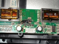
LCD TV inverter board for 4 lamps
The inverter device can be divided into functional blocks, from which it becomes clear that they are all similar to each other.
Below circuit diagram inverter belongs to lamp lighting. The lamps are connected using a capacitive circuit, which ensures their constant glow over time and provides effective brightness control. Transistors Q1, Q2 – turn on and turn on the inverter.
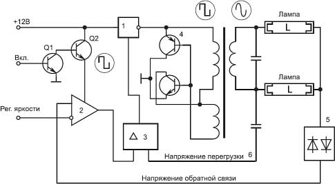
Inverter circuit diagram
Block (1) provides constant voltage to a self-oscillator with switches ((4) usually consists of two field-effect transistors, for example APM4010 and APM4015), which is turned on and controlled by PWM signals. The brightness control unit (2) and PWM (3) are usually constructed in one chip. A pulse-width modulator (PWM) controls the load in the secondary circuits and, if the lamps malfunction, does not allow the autogenerator 4 to turn on, which will protect against failure of the keys or transformer.
The required luminous flux is created by cold cathode fluorescent lamps (R) located behind the matrix and uniformly illuminate it.
PRINCIPLE OF OPERATION
The inverter must provide several functions:
- Change direct voltage into high-voltage alternating voltage;
- Provide brightness adjustment;
- Stabilize the lamp current and regulate it;
- Provide protection against short circuit and overload.
The matrix backlight inverter (for lamps) should provide a voltage of usually 600 volts with a load current of approximately 10 mA and provide a maximum screen brightness of about 250 cd/m2. In this case, the initial output voltage will be about 1600 V, and the protection response time will be from 1 to 1.3 s. For a confident start, the protection response time is selected 10 times longer than the start time.
When voltage is supplied from the power supply, a signal (usually 3-5 volts) to exit standby mode arrives approximately 2 seconds after turning on the TV from the main board and the backlight inverter enters the operating state.
The TV inverter controller provides a “soft” start when starting the inverter, as well as protection against short circuits and overloads. If the short circuit lasts less than 1 s, the inverter will continue to operate, otherwise it will shut down.
PWM pulses go to a converter, usually made according to a semi-bridge generator circuit with self-excitation and start the DC/DC converter and voltage for the backlight lamps appears on the secondary winding of the inverter transformer.
The small winding performs a feedback function in the TV inverter circuit.
When the lamps are “ignited” at the beginning of operation, the inverter voltage increases to 1600 V, and only then the inverter goes into operating mode. A faulty lamp, a capacitor in the secondary circuit or a short circuit in the secondary winding leads to generation failure.
The inverter voltage of an LCD TV is usually 24 or 48 volts (for a large diagonal). The laptop backlight is usually powered by a power supply voltage of 18 - 19 volts.
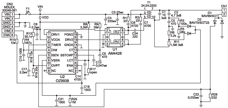
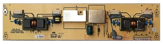
The board of such an inverter is small in size and located at the bottom of the screen. In this case, the controller U2 OZ9938 controls the keys U1 AM4428, contact CN1 goes to the lamp. Power goes through the VIN contacts, minus GND, brightness and power control goes to the DIM and ENA contacts.
INVERTER FOR LCD
In principle, there is no special difference other than a change in voltage. For example lcd inverter TVs often use 12 volts. The output can vary from 60 to 100 volts generally. This spread depends on the diagonal of the TV and, accordingly, the number of LEDs used for backlighting.
REPAIR
Anyone with a little knowledge of electronics and working with a soldering iron and a multimeter can repair the inverter with their own hands, since there is nothing extraordinary about it.
In terms of breakdowns, I can probably say that there are no major ones, everything breaks. Lamps, switches, transformers, controllers burn out.
Most often, the backlight inverter fails due to breakdowns of the electrolytic capacitors in the power supply and the power filters of the inverter itself. Losing capacity, swelling and closing the power circuit, they lower the voltage. The keys begin to work with greater overload and burn out.
IN LCD TVs More often than not, the diodes themselves burn out. When repairing a TV, you can replace the entire LED strip or check each one and replace it individually. For example, you have 3 stripes on your TV LED strips 7 diodes on each. It is known that their supply voltage is 70 volts. We divide and get 3.3 volts, look for one with a power of 1 watt to ensure normal brightness and make a replacement.
The models of modern inverters are very diverse, but the principles of their construction and operation are almost the same, and this simplifies their repair.