Do you need LED backlighting on your TV? In this case, the backlight will work when the device is connected to the network. We independently create a power supply circuit and adjust the backlight brightness
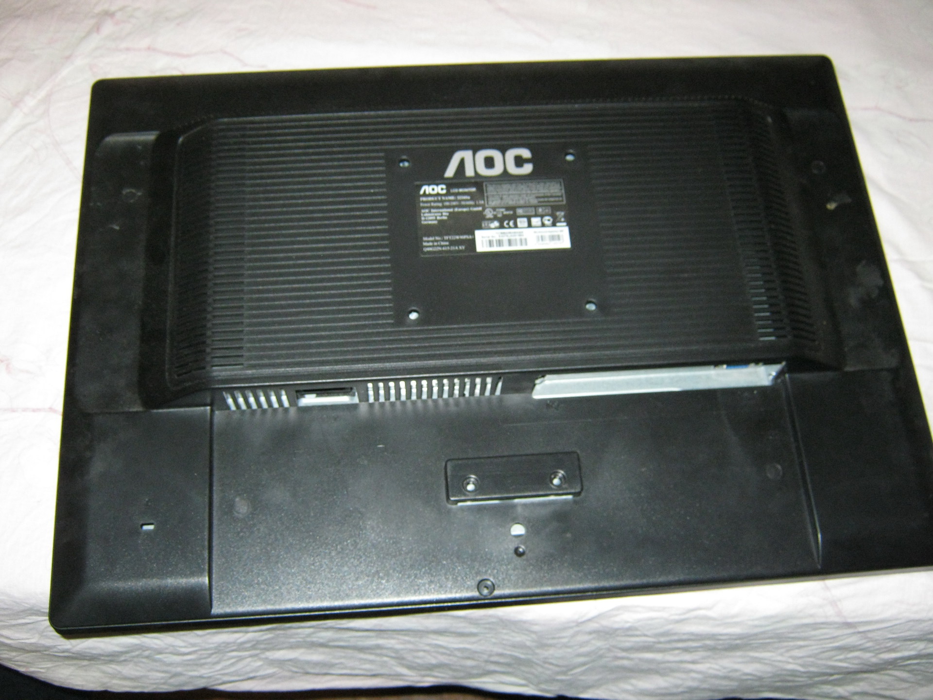
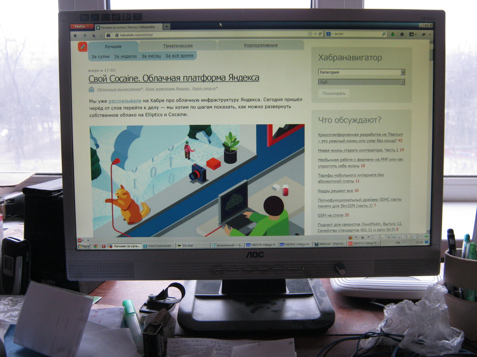
Time passes unnoticed and seemingly recently purchased equipment is already breaking down. So, having worked their 10,000 hours, the lamps of my monitor (AOC 2216Sa) gave up their life. At first, the backlight did not turn on the first time (after turning on the monitor, the backlight turned off after a few seconds), which was solved by turning the monitor on/off again; over time, the monitor had to be turned off/off 3 times, then 5, then 10, and at some point it could not turn on the backlight, regardless of the number of attempts to turn it on. The lamps brought to the light of day turned out to have blackened edges and were legally thrown into scrap. An attempt to install replacement lamps (new lamps of the appropriate size were purchased) was unsuccessful (the monitor was able to turn on the backlight several times, but quickly went into on-off mode again) and finding out the reasons for what the problem could be in the electronics of the monitor led me to the idea that it will be easier to assemble your own monitor backlight using LEDs than to repair the existing inverter circuit for CCFL lamps, especially since there have already been articles on the Internet showing the fundamental possibility of such a replacement.
Disassembling the monitor
Many articles have already been written on the topic of disassembling a monitor; all monitors are very similar to each other, so in brief:1. Unscrew the monitor delivery mount and the only bolt at the bottom that holds the back wall of the case
2. At the bottom of the case there are two grooves between the front and back of the case, insert a flat-head screwdriver into one of them and begin to remove the cover from the latches along the entire perimeter of the monitor (simply turning the screwdriver carefully around its axis and thereby lifting the case cover). There is no need to exert excessive effort, but it is difficult to remove the case from the latches only the first time (during the repair I opened it many times, so the latches became much easier to remove over time).
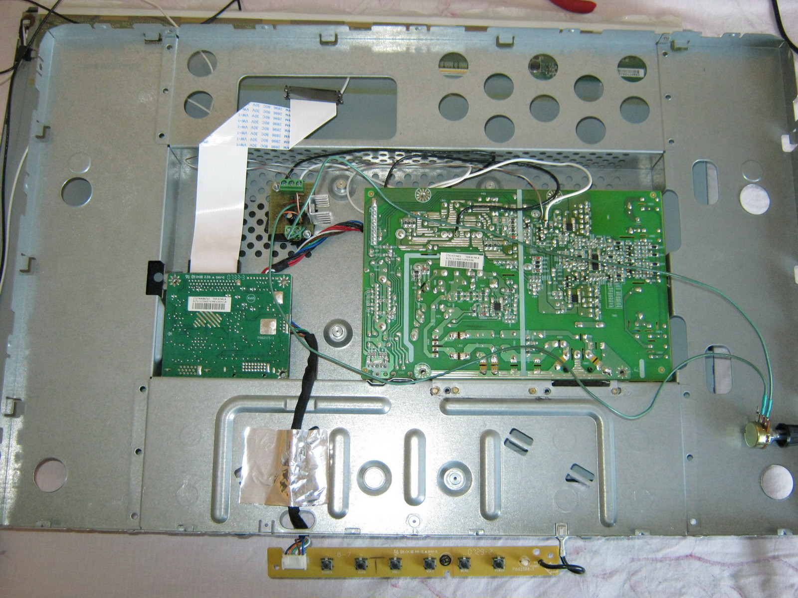
3. We have a view of the installation of the internal metal frame in the front of the case:
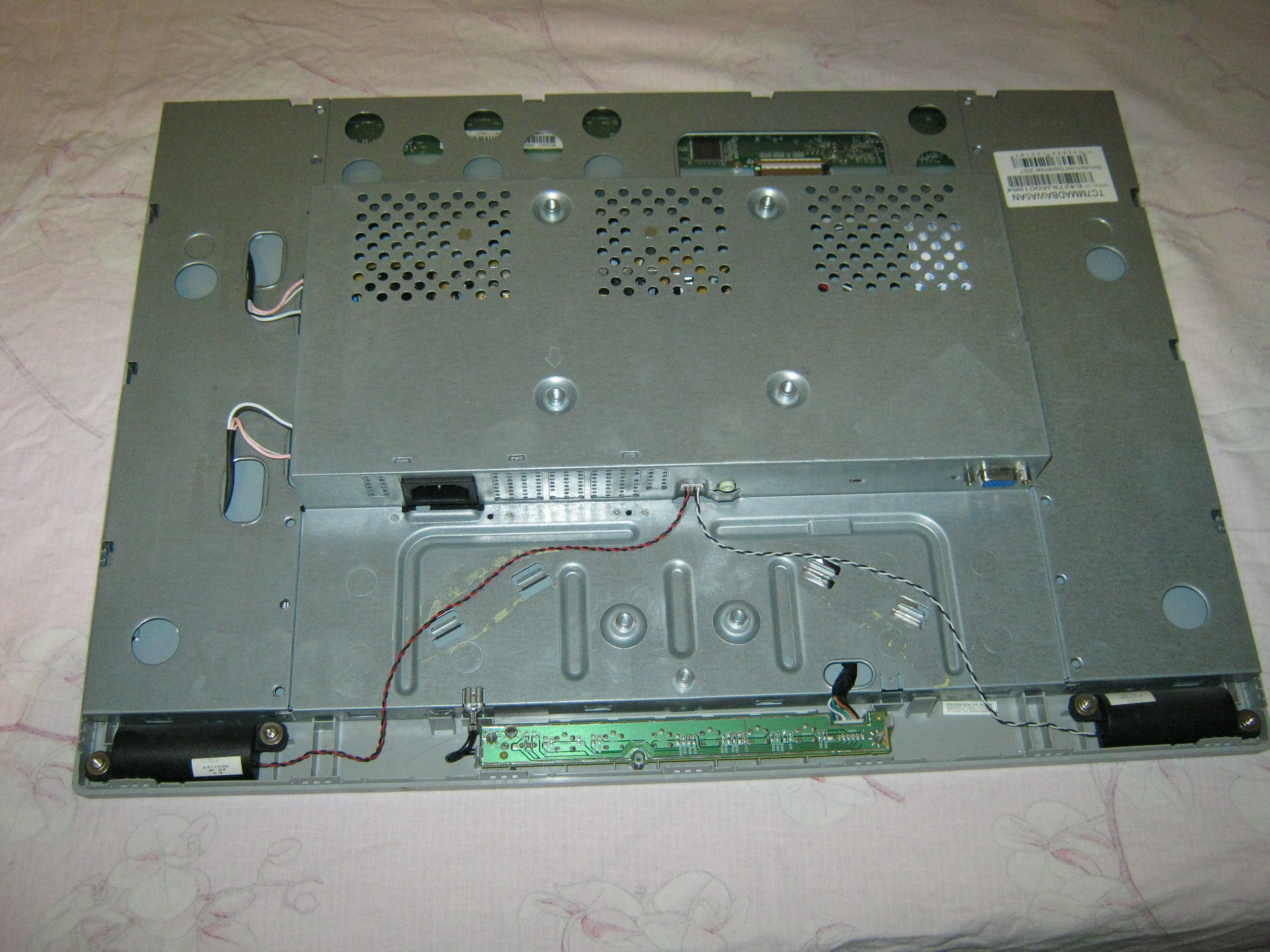
We take out the board with the buttons from the latches, take out (in my case) the speaker connector and, bending the two latches at the bottom, take out the inner metal case.
4. On the left you can see 4 wires connecting the backlight lamps. We take them out by squeezing them slightly, because... To prevent it from falling out, the connector is made in the form of a small clothespin. We also remove the wide cable going to the matrix (at the top of the monitor), squeezing its connector on the sides (since the connector has side latches, although this is not obvious at first glance at the connector):
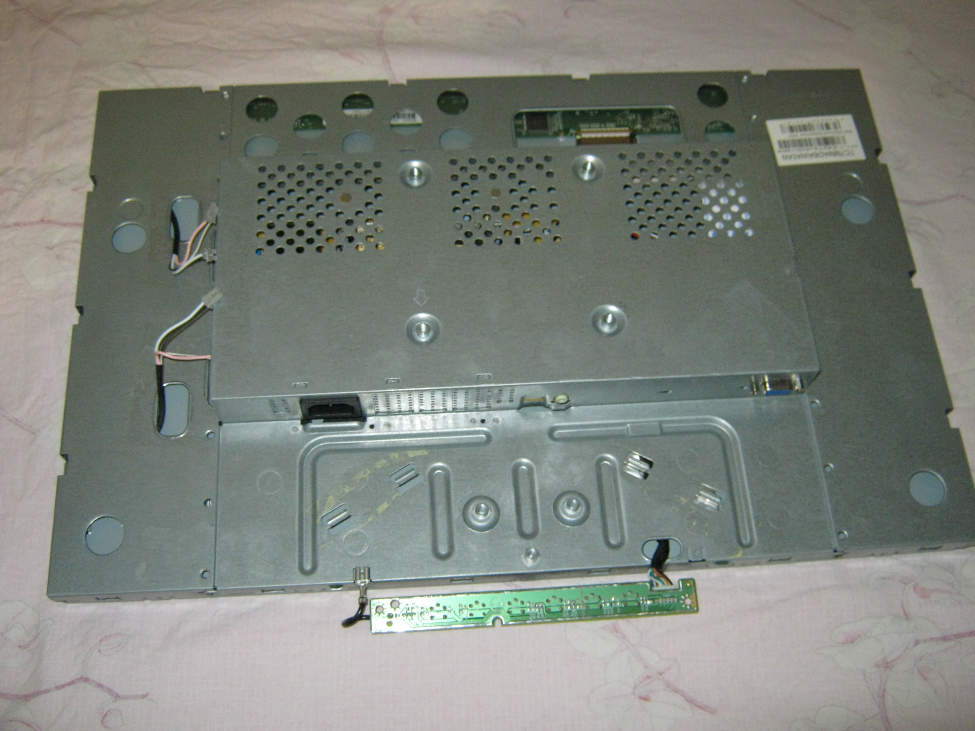
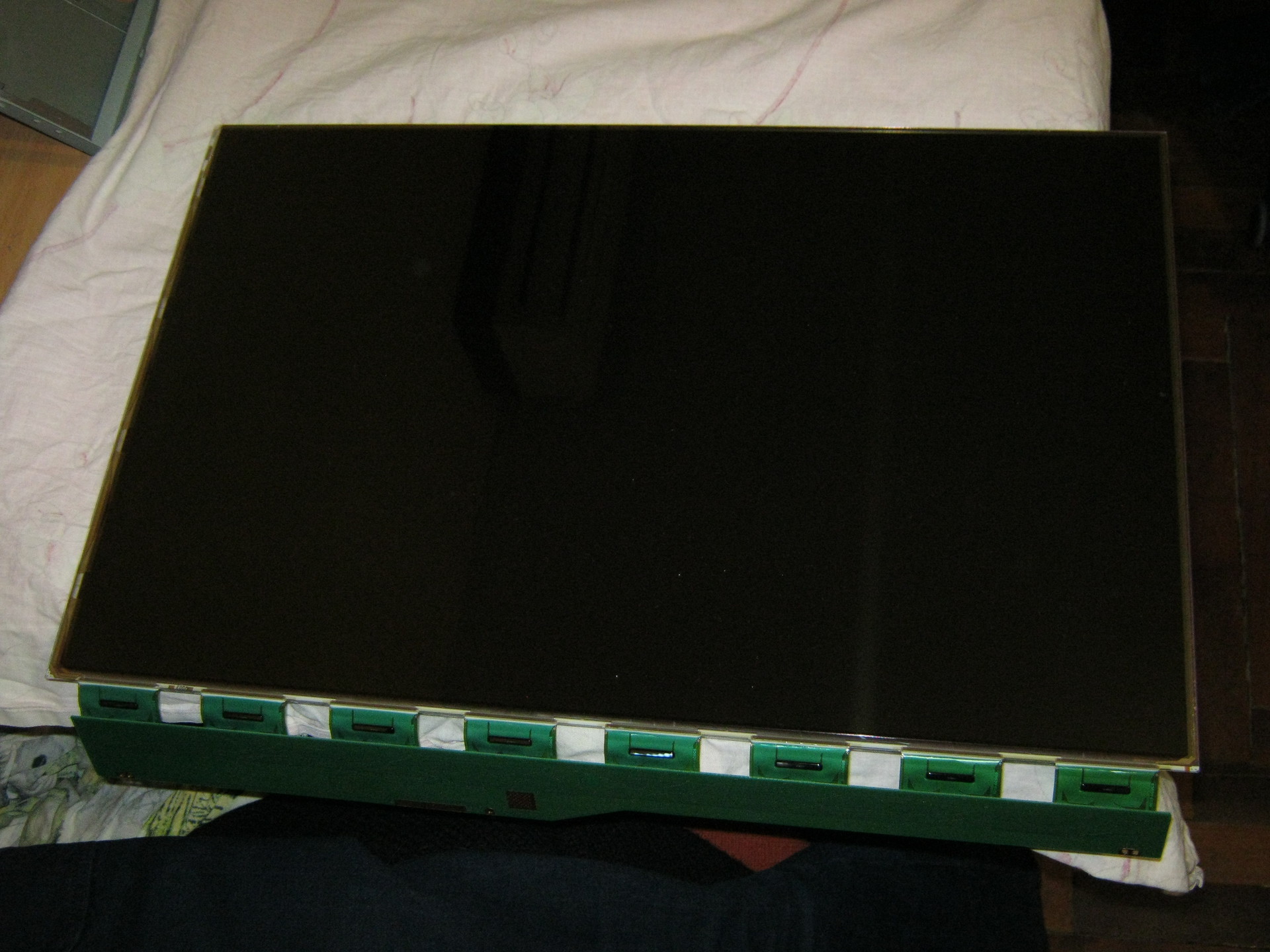
5. Now you need to disassemble the “sandwich” containing the matrix itself and the backlight:
There are latches along the perimeter that can be opened by lightly prying with the same flat screwdriver. First, the metal frame holding the matrix is removed, after which you can unscrew three small bolts (a regular Phillips screwdriver will not work due to their miniature size, you will need a particularly small one) holding the matrix control board and the matrix can be removed (it is best to place the monitor on a hard surface, such as a table covered with the fabric matrix facing down, unscrewing the control board, put it on the table unfolded through the end of the monitor and simply lift the case with the backlight, lifting it vertically up, and the matrix will remain lying on the table. You can cover it with something so that it does not gather dust, and assemble it exactly the opposite way order - i.e. cover the matrix lying on the table with the assembled case with backlight, wrap the cable through the end to the control board and, screwing the control board, carefully lift the assembled unit).
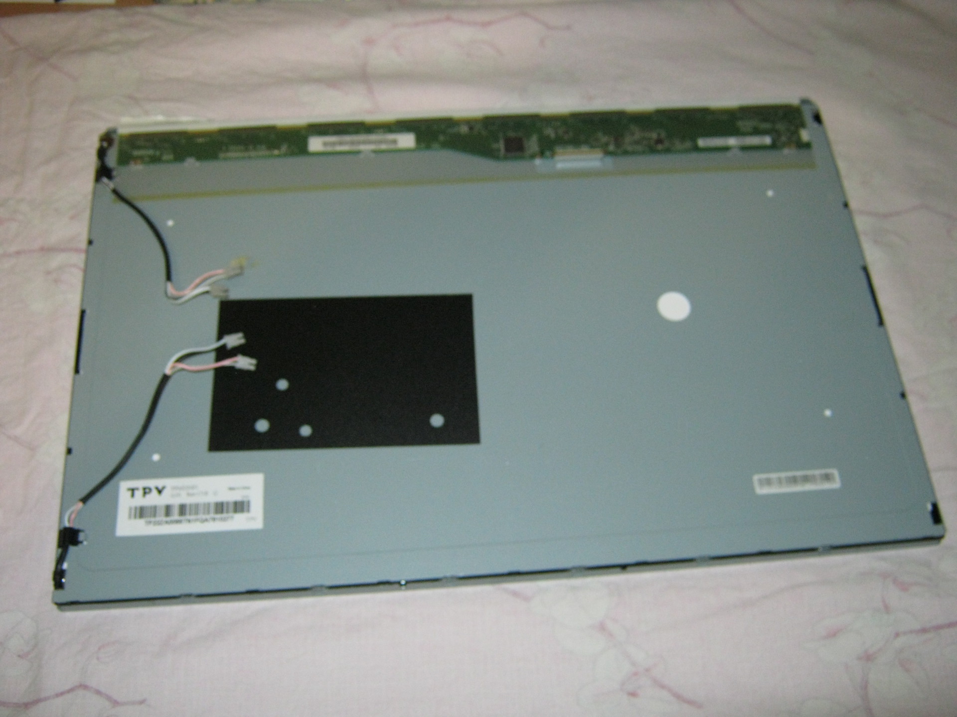
The matrix is obtained separately:
And the backlit block separately:
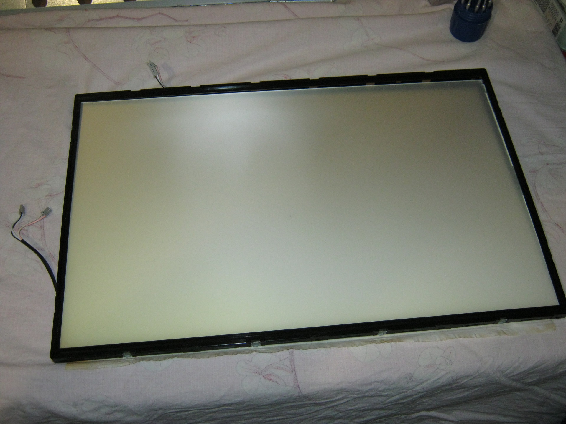
The backlit unit is disassembled in the same way, only instead of a metal frame, the backlight is held by a plastic frame, which simultaneously positions the plexiglass used to diffuse the backlight light. Most of the latches are located on the sides and are similar to those that held the metal frame of the matrix (they open by prying them off with a flat-head screwdriver), but on the sides there are several latches that open “inward” (you need to press on them with a screwdriver so that the latches go inside the case).
At first I remembered the position of all the parts to be removed, but then it turned out that it would not be possible to assemble them “wrongly” and even if the parts look absolutely symmetrical, the distances between the latches on different sides of the metal frame and the locking protrusions on the sides of the plastic frame holding the backlight will not allow them to be assembled “wrongly” "
That's all - we disassembled the monitor.
LED strip lighting
At first it was decided to make the backlight from LED strip with white LEDs 3528 - 120 LEDs per meter. The first thing that turned out to be is that the width of the tape is 9 mm, and the width of the backlight lamps (and the seat for the tape) is 7 mm (in fact, there are backlight lamps of two standards - 9 mm and 7 mm, but in my case they were 7 mm). Therefore, after examining the tape, it was decided to cut 1 mm from each edge of the tape, because this did not affect the conductive paths on the front part of the tape (and on the back, along the entire tape, there are two wide power cores, which will not lose their properties due to a decrease of 1 mm over a backlight length of 475 mm, since the current will be small). No sooner said than done: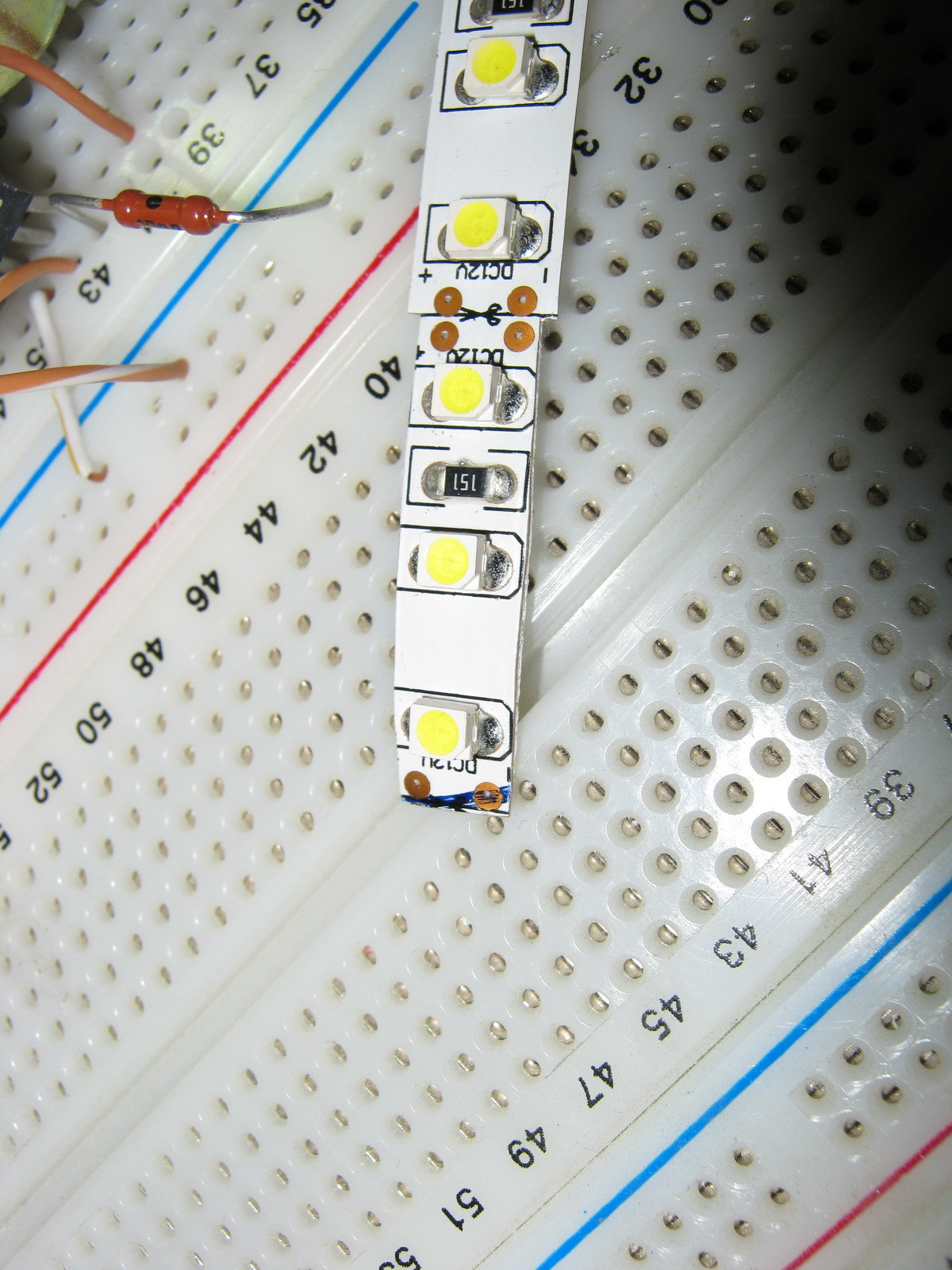
In the same way, the LED strip is carefully trimmed along its entire length (the photo shows an example of what happened before and what happened after trimming).
We will need two strips of 475 mm tape (19 segments of 3 LEDs per strip).
I wanted the monitor backlight to work the same way as the standard one (i.e. it was turned on and off by the monitor controller), but I wanted to adjust the brightness “manually”, as on old CRT monitors, because This is a frequently used function, and I got tired of navigating through on-screen menus pressing several keys every time (on my monitor, the right-left keys do not adjust the monitor modes, but the volume of the built-in speakers, so the modes had to be changed through the menu every time). To do this, I found a manual for my monitor on the Internet (for those who need it, it is attached at the end of the article) and on the page with the Power Board, according to the diagram, +12V, On, Dim and GND were found that are of interest to us.
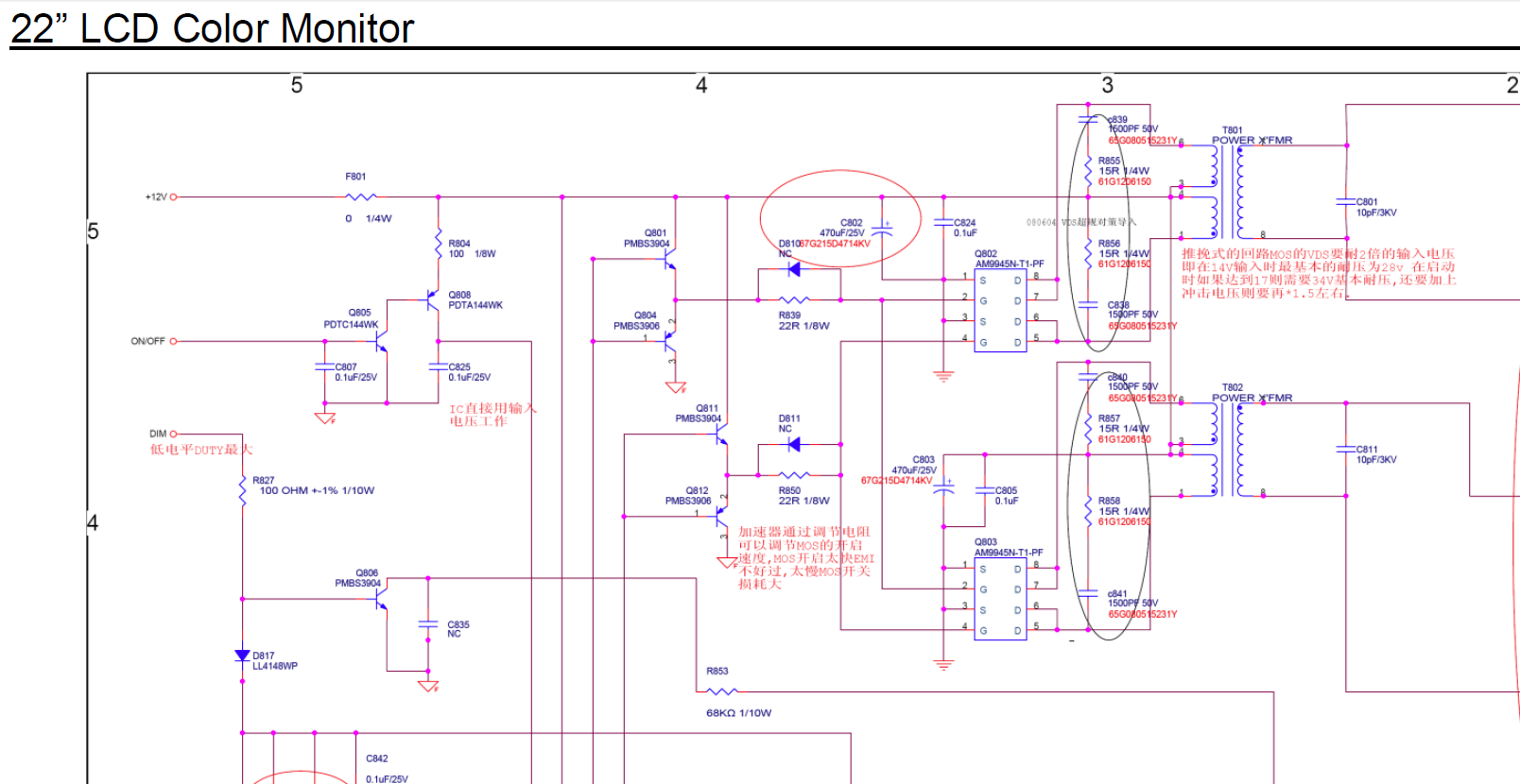
On - signal from the control board to turn on the backlight (+5V)
Dim - PWM backlight brightness control
+12V turned out to be far from 12, but somewhere around 16V without backlight load and somewhere around 13.67V with load
It was also decided not to make any PWM adjustments to the backlight brightness, but to power the backlight DC(at the same time, the issue is resolved that on some monitors the PWM backlight operates at a not very high frequency and for some this makes the eyes a little more tired). In my monitor, the “native” PWM frequency was 240 Hz.
Further on the board we found contacts to which the On signal is supplied (marked in red) and +12V to the inverter unit (the jumper that must be removed to de-energize the inverter unit is marked in green). (photo can be enlarged to see notes):
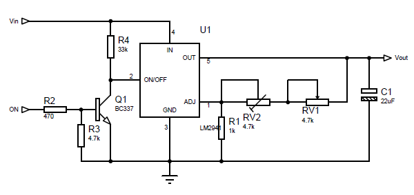
The LM2941 linear regulator was used as the basis for the control circuit, mainly because at a current of up to 1A it had a separate On/Off control pin, which was supposed to be used to control the backlight on/off with the On signal from the monitor control board. True, in LM2941 this signal is inverted (that is, there is voltage at the output when the On/Off input is zero potential), so we had to assemble an inverter on one transistor to match the direct On signal from the control board and the inverted input of LM2941. The scheme does not contain any other excesses:
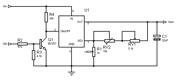
The output voltage for LM2941 is calculated using the formula:
Vout = Vref * (R1+R2)/R1
Where Vref = 1.275V, R1 in the formula corresponds to R1 in the diagram, and R2 in the formula corresponds to a pair of resistors RV1+RV2 in the diagram (two resistors were introduced for smoother brightness adjustment and reducing the range of voltages regulated by the variable resistor RV1).
I took 1kOhm as R1, and the selection of R2 is carried out according to the formula:
R2=R1*(Vout/Vref-1)
The maximum voltage we need for the tape is 13V (I took a little more than the nominal 12V so as not to lose brightness, and the tape will survive such a slight overvoltage). Those. maximum value R2 = 1000*(13/1.275-1) = 9.91 kOhm. The minimum voltage at which the tape still glows at least somehow is about 7 volts, i.e. minimum value R2 = 1000*(7/1.275-1) = 4.49 kOhm. Our R2 consists of a variable resistor RV1 and a multi-turn trimming resistor RV2. The resistance of RV1 is 9.91 kOhm - 4.49 kOhm = 5.42 kOhm (we select the closest value of RV1 - 5.1 kOhm), and RV2 is set to approximately 9.91-5.1 = 4.81 kOhm (in fact, it is best to first assemble the circuit, set the maximum resistance of RV1 and measure the voltage at At the output of LM2941, set the resistance RV2 so that the output has the required maximum voltage (in our case, about 13V).
Installation of LED strip
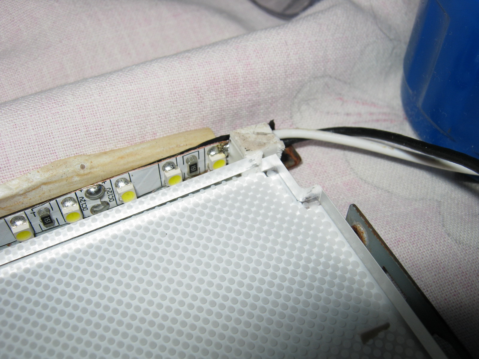
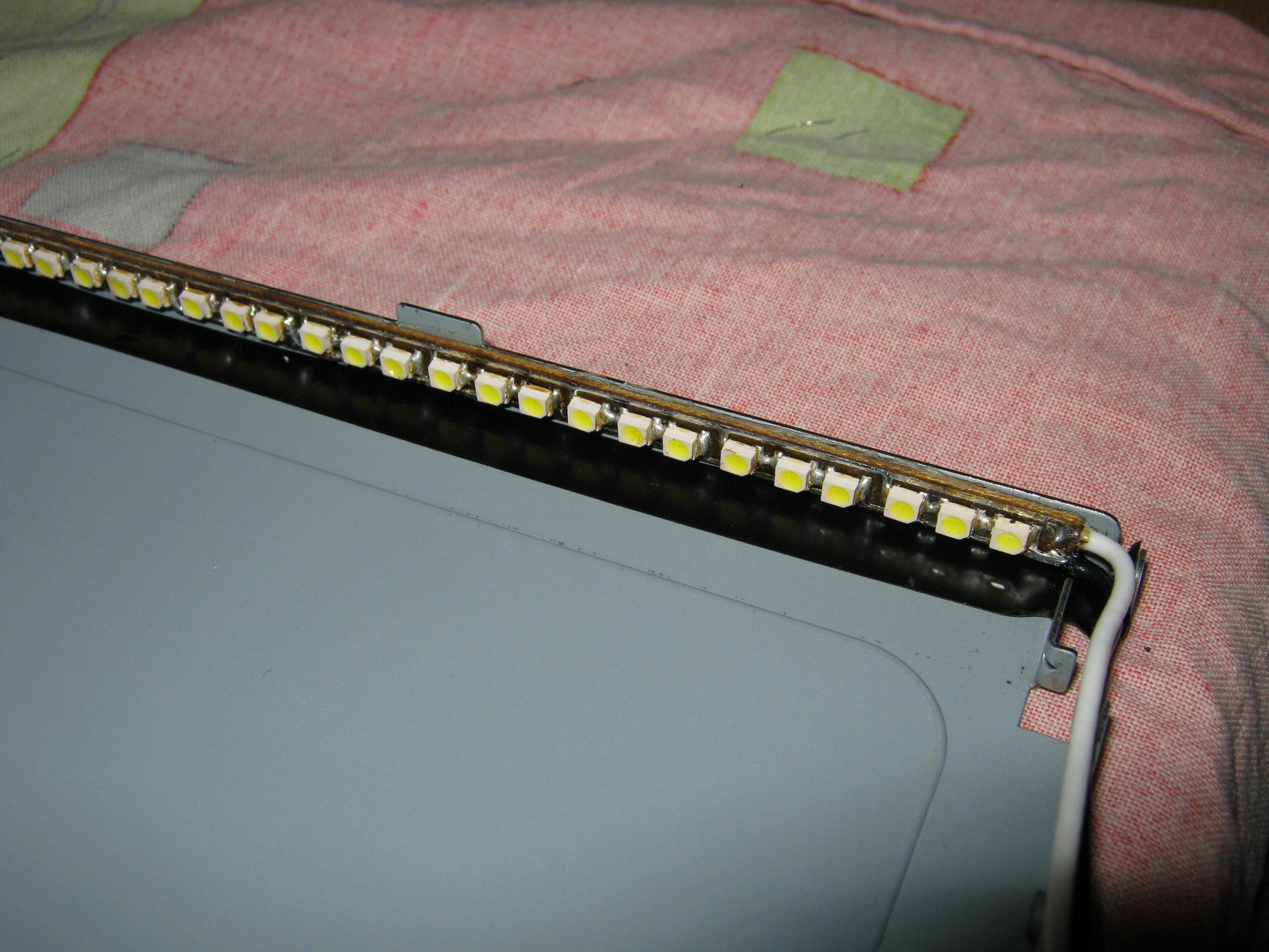
Since after cutting the tape by 1 mm, the power conductors were exposed at the ends of the tape, I pasted electrical tape (unfortunately, not blue but black) onto the body in the place where the tape would be glued. The tape is glued on top (it is good to warm the surface with a hairdryer, because the tape sticks much better to a warm surface):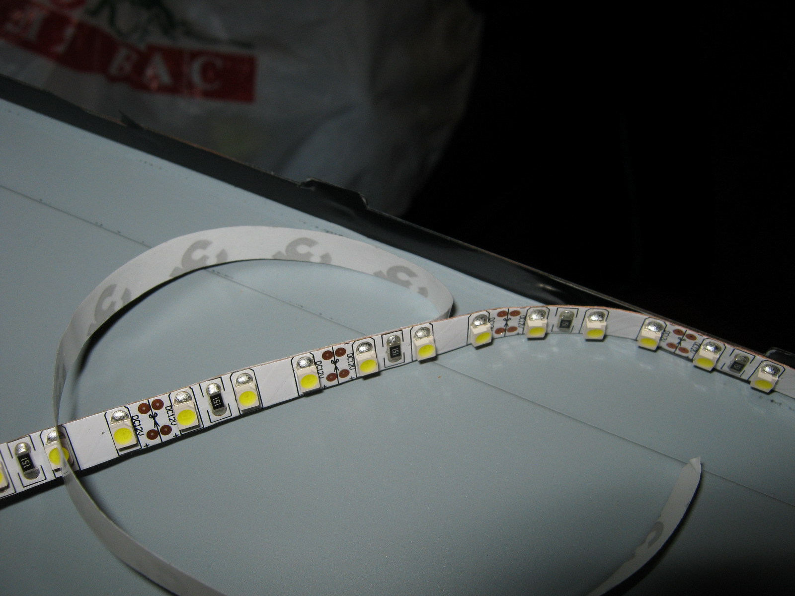
Next, the back film, plexiglass and light filters that lay on top of the plexiglass are mounted. Along the edges I supported the tape with pieces of eraser (so that the edges on the tape did not come off):
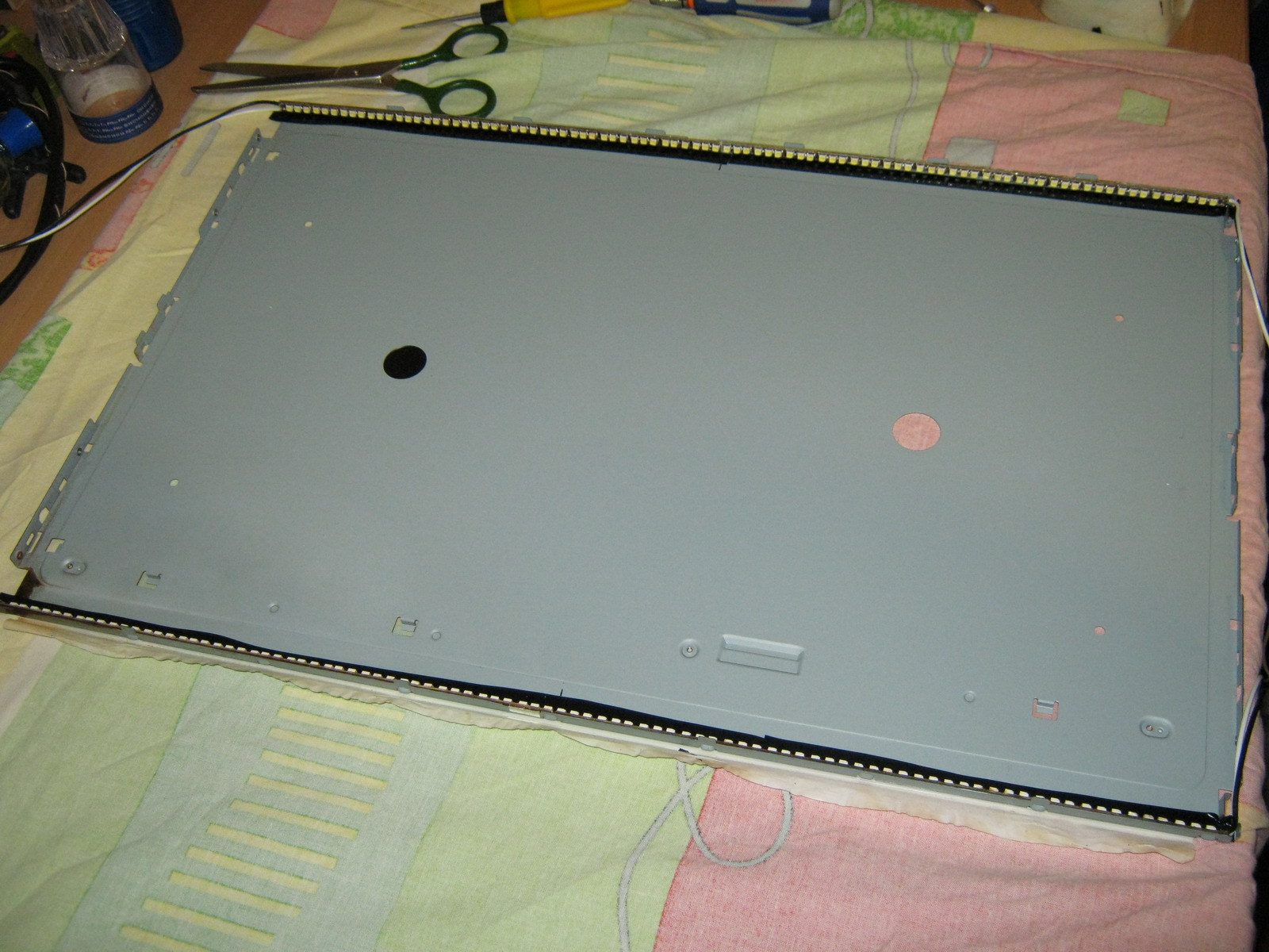
After that, the backlight unit is assembled in the reverse order, the matrix is installed in place, and the backlight wires are brought out.
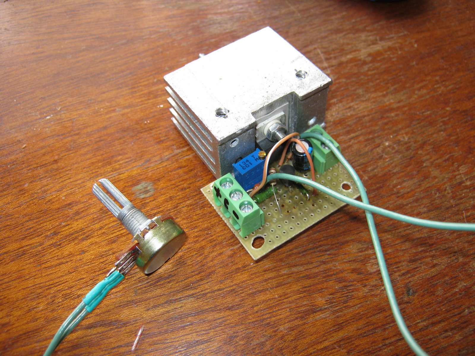
The circuit was assembled on a breadboard (due to simplicity, I decided not to wire the board), and was fastened with bolts through holes in the back wall of the metal monitor case:
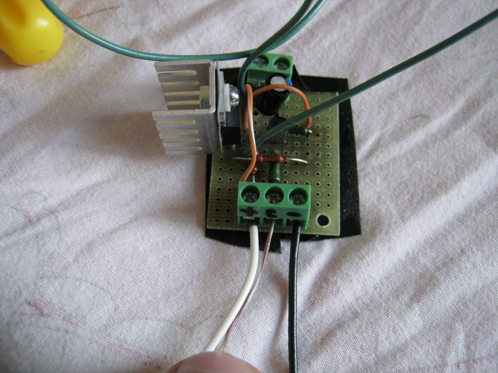
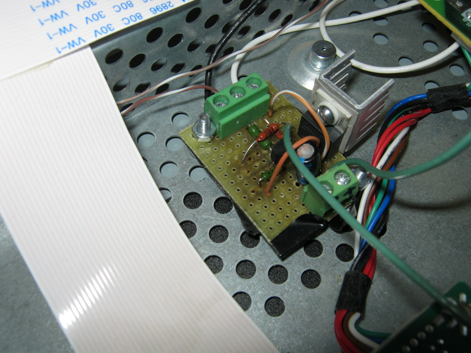
Power and control signal On were supplied from the power supply board:
The estimated power allocated to the LM2941 is calculated using the formula:
Pd = (Vin-Vout)*Iout +Vin*Ignd
For my case, it is Pd = (13.6-13)*0.7 +13.6*0.006 = 0.5 Watt, so it was decided to make do with the smallest radiator for the LM2941 (placed through a dielectric pad since it is not isolated from the ground in the LM2941).
The final assembly showed that the design was fully functional: 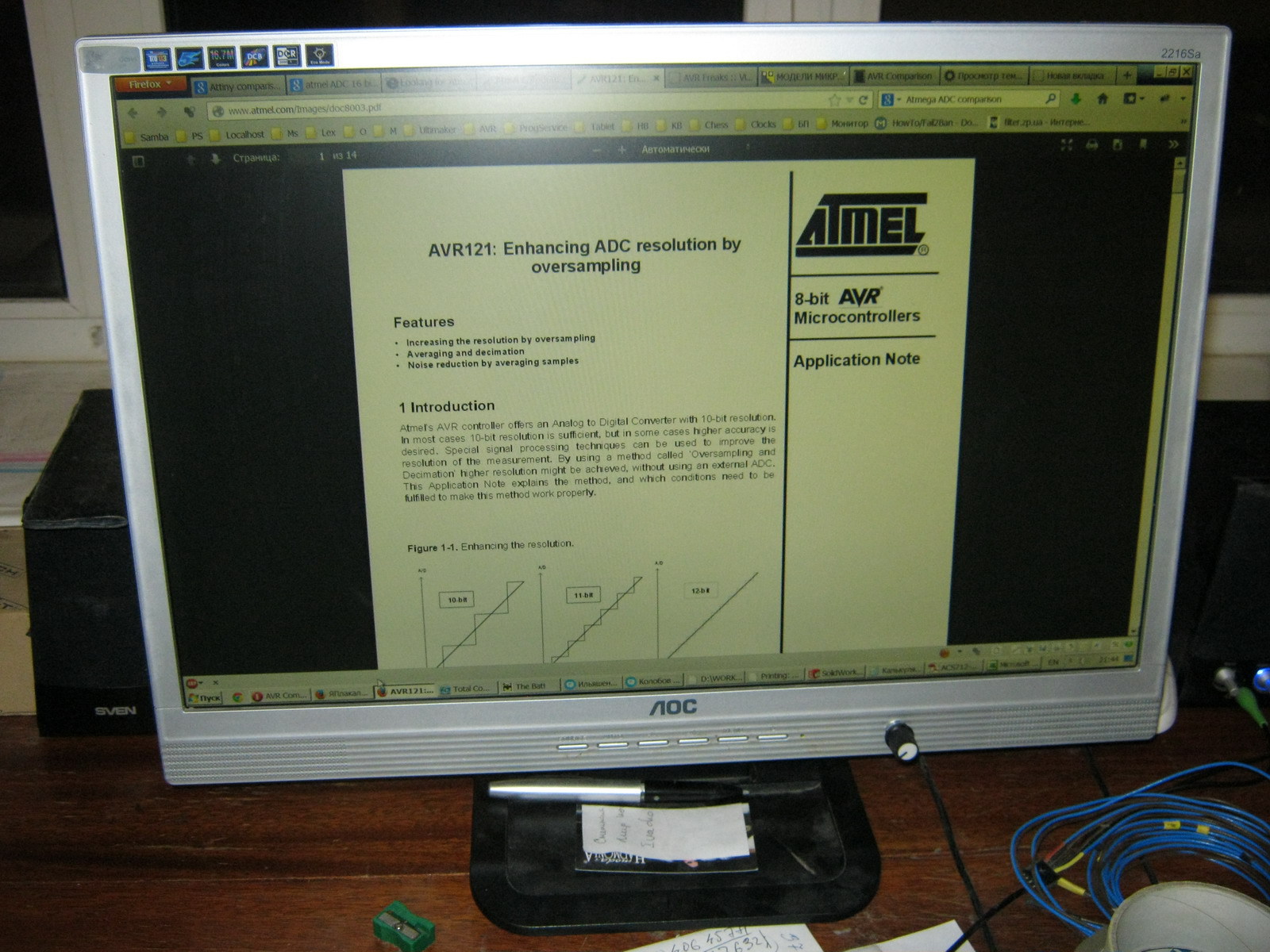
Among the advantages:
- Uses standard LED strip
- Simple control board
- Insufficient backlight brightness in bright daylight (the monitor is placed in front of a window)
- The LEDs in the strip are not spaced closely enough, so small cones of light from each individual LED are visible near the top and bottom edges of the monitor
- The white balance is a little off and goes slightly greenish (most likely this can be solved by adjusting the white balance of either the monitor itself or the video card)
Adjusting brightness using PWM
For those Habro residents who, unlike me, do not remember with nostalgia the analogue brightness and contrast control knobs on old CRT monitors, you can make control from the standard PWM generated by the monitor control board without moving any additional controls outside (without drilling the monitor body). To do this, it is enough to assemble an AND-NOT circuit on two transistors at the On/Off input of the regulator and remove the brightness control at the output (set the output voltage to constant 12-13V). Modified scheme: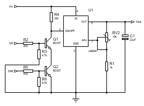
The resistance of the trimming resistor RV2 for a voltage of 13V should be around 9.9 kOhm (but it is better to set it exactly when the regulator is on)
More dense LED backlight
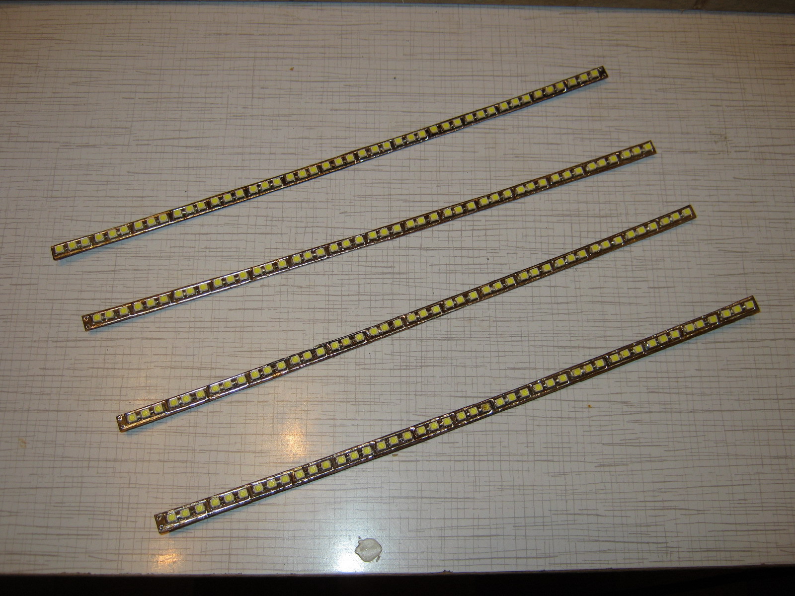
To solve the problem of insufficient brightness (and at the same time uniformity) of the backlight, it was decided to install more LEDs and more often. Since it turned out that buying LEDs individually is more expensive than buying 1.5 meters of strip and desoldering them from there, a more economical option was chosen (desoldering LEDs from the strip).The 3528 LEDs themselves are placed on 4 strips 6 mm wide and 238 mm long, 3 LEDs in series in 15 parallel assemblies on each of the 4 strips (the layout of the boards for the LEDs is included). After soldering the LEDs and wires, the following is obtained:
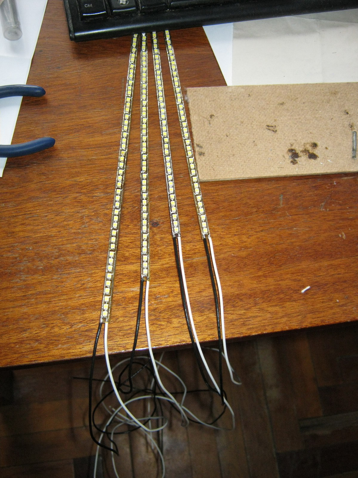
The strips are laid in twos at the top and bottom with wires to the edge of the monitor at the joint in the center:
The nominal voltage on the LEDs is 3.5V (range from 3.2 to 3.8 V), so an assembly of 3 series LEDs should be powered with a voltage of about 10.5V. So the controller parameters need to be recalculated:
The maximum voltage we need for the tape is 10.5V. Those. maximum value R2 = 1000*(10.5/1.275-1) = 7.23 kOhm. The minimum voltage at which the LED assembly still glows at least somehow is about 4.5 volts, i.e. minimum value R2 = 1000*(4.5/1.275-1) = 2.53 kOhm. Our R2 consists of a variable resistor RV1 and a multi-turn trimming resistor RV2. The resistance of RV1 is 7.23 kOhm - 2.53 kOhm = 4.7 kOhm, and RV2 is set to approximately 7.23-4.7 = 2.53 kOhm and adjusted in the assembled circuit to obtain 10.5 V at the output of LM2941 at the maximum resistance of RV1.
One and a half times more LEDs consume 1.2A of current (nominally), so the power dissipation on the LM2941 will be equal to Pd = (13.6-10.5)*1.2 +13.6*0.006 = 3.8 Watt, which already requires a more solid heatsink for heat removal:
We collect, connect, we get much better:
Advantages:
- Quite high brightness (possibly comparable, and perhaps even superior to the brightness of the old CCTL backlight)
- The absence of light cones at the edges of the monitor from individual LEDs (LEDs are located quite often and the backlight is uniform)
- Still a simple and cheap control board
- The issue with the white balance, which goes into greenish tones, has not been resolved
- LM2941, although with a large heatsink, gets hot and heats everything inside the case
Control board based on step-down regulator
To eliminate the heating problem, it was decided to assemble a brightness controller based on a Step-down voltage regulator (in my case, an LM2576 with a current of up to 3A was chosen). It also has an inverted On/Off control input, so for matching there is the same inverter on one transistor:Coil L1 affects the efficiency of the converter and should be 100-220 µH for a load current of about 1.2-3A. The output voltage is calculated using the formula:
Vout=Vref*(1+R2/R1)
Where Vref = 1.23V. For a given R1, you can obtain R2 using the formula:
R2=R1*(Vout/Vref-1)
In calculations, R1 is equivalent to R4 in the circuit, and R2 is equivalent to RV1+RV2 in the circuit. In our case, to adjust the voltage in the range from 7.25V to 10.5V, we take R4 = 1.8 kOhm, variable resistor RV1 = 4.7 kOhm and trimming resistor RV2 at 10 kOhm with an initial approximation of 8.8 kOhm (after assembling the circuit, it is best to set its exact value by measuring the voltage at the output of LM2576 at maximum resistance RV1).
I decided to make a board for this regulator (the dimensions did not matter, since there is enough space in the monitor to mount even a large board): 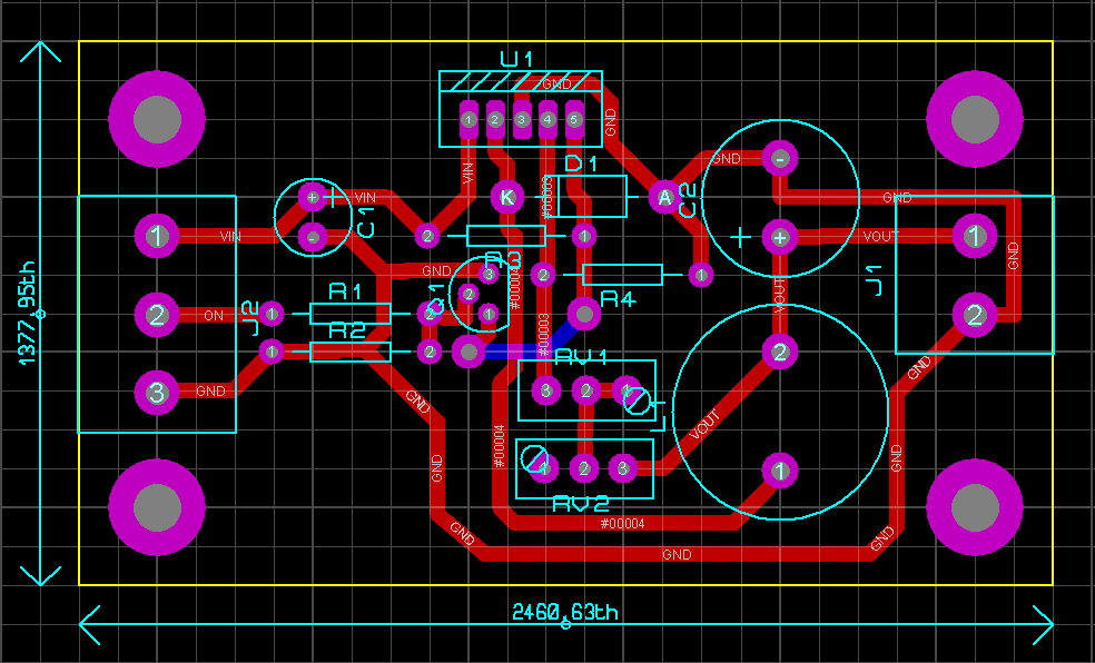
Control board assembly: 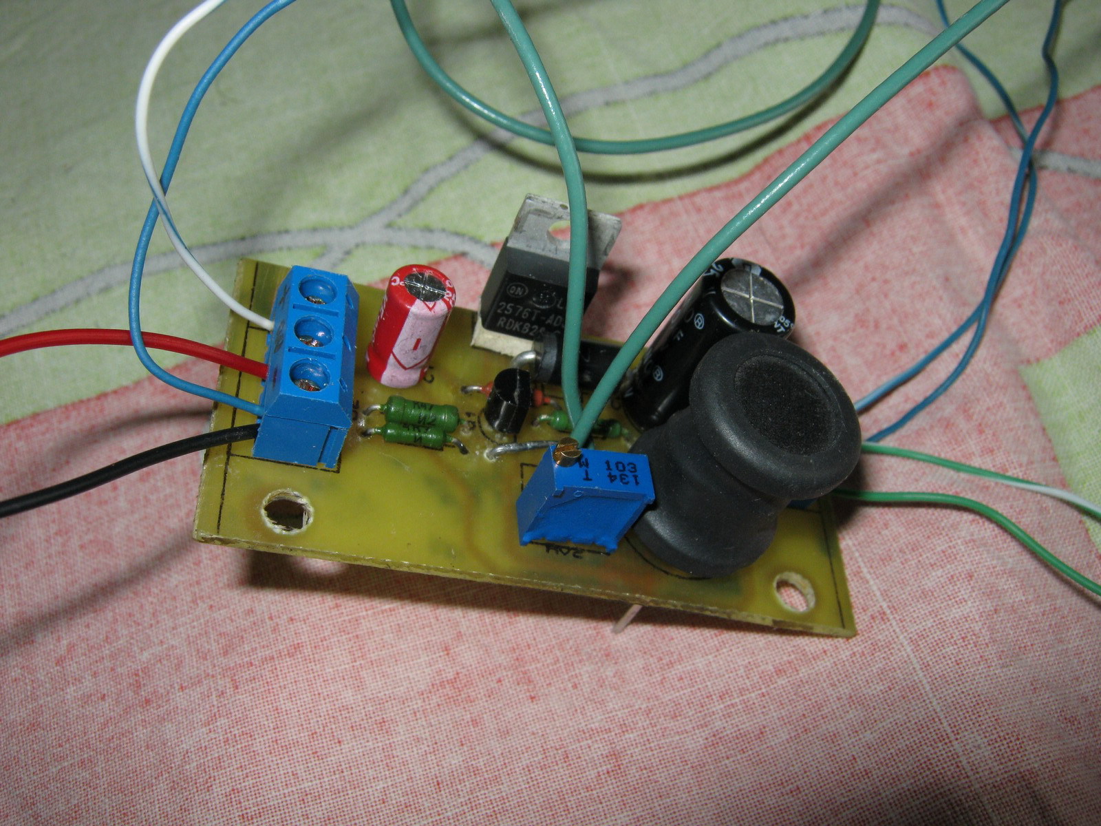
After installation in the monitor: ![]()
Everyone is here: 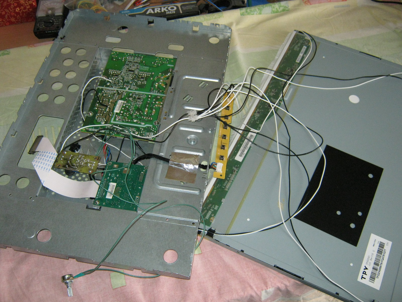
After assembly everything seems to work: 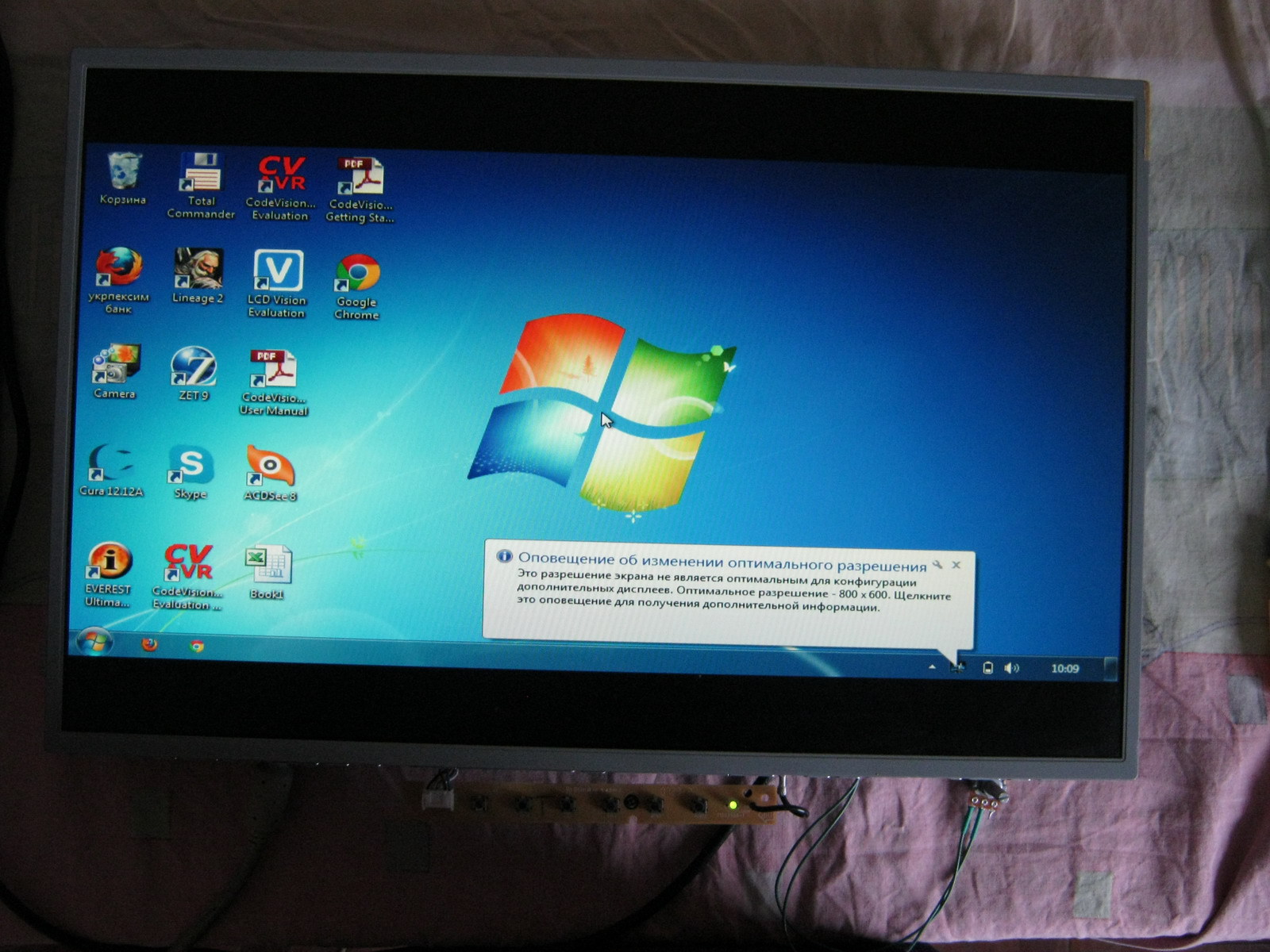
Final option: 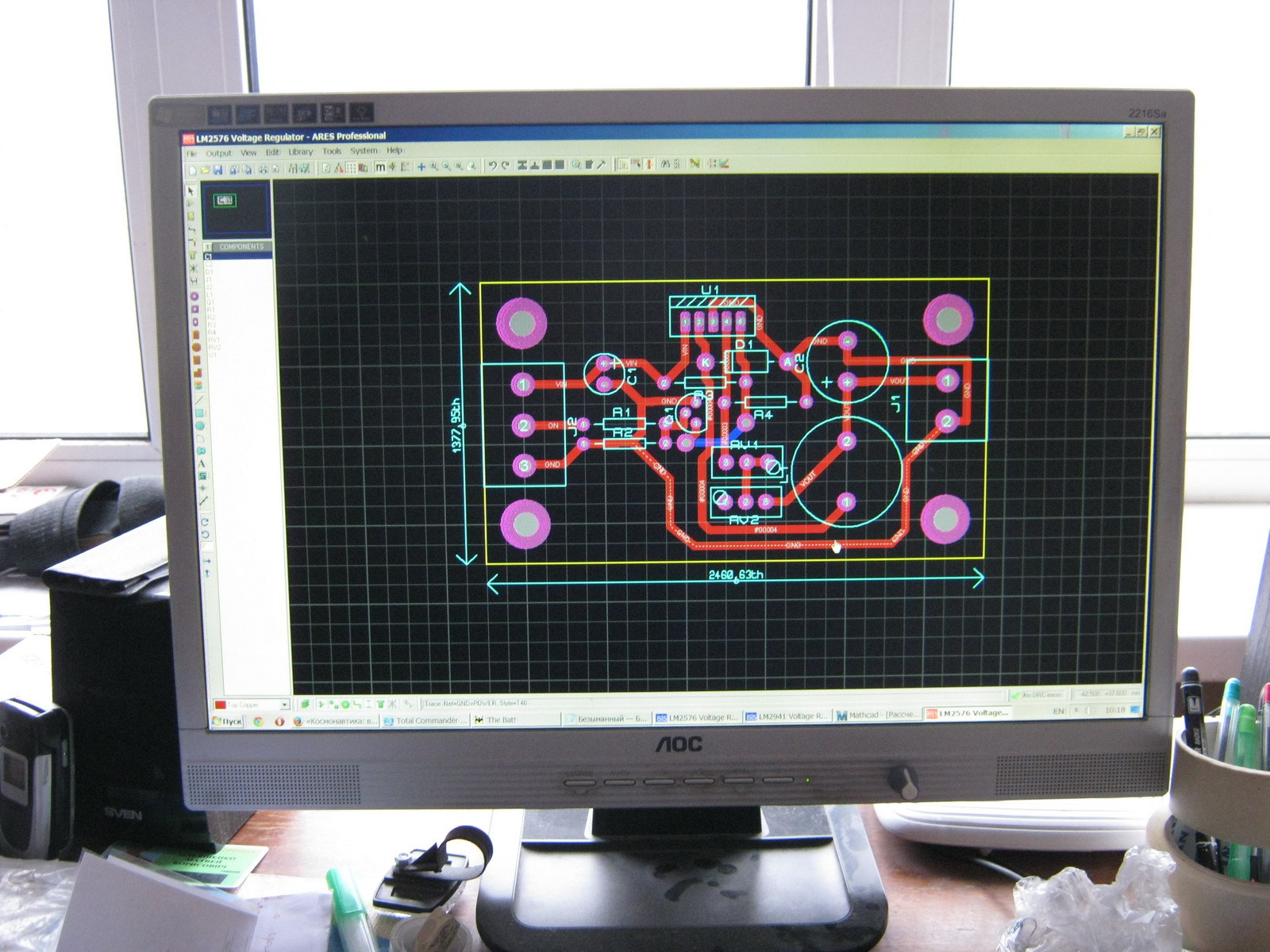
Advantages:
- Sufficient brightness
- Step-down regulator does not heat up and does not warm up the monitor
- There is no PWM, which means nothing blinks at any frequency
- Analogue (manual) brightness control
- No restrictions on minimum brightness (for those who like to work at night)
- The white balance is slightly shifted towards green tones (but not much)
- At low brightness (very low), unevenness in the glow of LEDs of different assemblies is visible due to the spread of parameters
Improvement options:
- White balance is adjustable both in the monitor settings and in the settings of almost any video card
- You can try installing other LEDs that will not noticeably disrupt the white balance
- To eliminate the uneven glow of LEDs at low brightness, you can use: a) PWM (adjust the brightness using PWM by always supplying the rated voltage) or b) connect all the LEDs in series and power them with an adjustable current source (if you connect all 180 LEDs in series, you will need 630V and 20mA), then the same current should pass through all the LEDs, and each one will have its own voltage drop; the brightness is regulated by changing the current and not the voltage.
- If you want to make a PWM-based circuit for LM2576, you can use a NAND circuit at the On/Off input of this Step-down regulator (similar to the above circuit for LM2941), but it is better to put a dimmer in the gap of the negative wire of the LEDs via a logic-level mosfet
LED backlighting is another characteristic of TVs and monitors, which has recently complicated the buyer’s choice, requiring him to think twice and make a responsible decision... The fact is that LCD TVs are becoming more and more numerous, and their types are increasing time multiply.
Indeed, when purchasing a TV, you want not to make a mistake, not to buy something that represents yesterday or the day before yesterday, which you will soon no longer be able to use...
Fortunately, there are no big difficulties in this issue; its importance is greatly exaggerated - more on this below on the page...
Eat good rule: When buying a TV, it is recommended to pay less attention to the names of the technologies used, and be more guided by your impressions of its appearance and image quality.
At the same time, of course, a more modern (and expensive) TV will in most cases be of better quality.
Best results In terms of image quality today, perhaps, the backlight type is Direct (Full) LED. Moreover, it is being improved all the time - now this technology can use a very large number of LEDs, which, naturally, has a very positive effect.
Edge LED or its derivatives also show increasingly better characteristics, making it possible to make TVs very thin.
In both cases in best models TVs also use the “Local Dimming” method - Local Dimming. In LG TVs, the backlight using it is called LED plus.
The LCD elements that make up LCD TV panels will not produce images on their own unless they are backlit. Therefore, one or another type of illumination in modern TVs definitely present. It should be borne in mind that technologies are constantly being improved, and the type of illumination with the same or similar name next year may be very different in execution from last year. For example, Full LED screens are now produced almost as thin as Edge LED.
Among the types of TV backlights used or used by SONY are the following:
CCFL (Cold Cathode Fluorescent Lamp).
WCG-CCFL (Wide Color Gamut Cold Cathode Fluorescent Lighting).
RGB LED, or dynamic rgb led (Provides color illumination of individual fragments of the monitor or TV screen. Potentially a very promising technology, since in theory it makes it possible to illuminate the desired area of the screen with a certain color. In practice, its theoretical advantages compared to other types cannot always be translated into life. For more details, see below on the page).
Full LED. Another name is Direct LED (backlit diodes are located behind the screen evenly over its entire area. This simplifies control and improves quality. But it negatively affects the thickness of the screen.) - Edge LED (The liquid crystal screen is illuminated by white LEDs installed at the top and bottom or on the sides Allows the production of very thin Slim TVs).
Dynamic Edge LED (In addition, Local Dimming technology is used, which controls the amount of light of individual groups of LEDs depending on the displayed image).
Intelligent Dynamic LED. Another name is Full LED or Direct LED (Compared to previous technologies, many more white illuminating LEDs are used, located directly behind the TV screen evenly across its entire area and illuminating the image. By controlling the glow of individual blocks of LEDs, the system can illuminate specific areas of the image, leaving others dark. This technology simplifies operation and improves quality, but has a negative impact on screen thickness.)
Other TV manufacturers, Samsung, Sharp, LG or Toshiba use different technologies to varying degrees. Accordingly, the TV backlight options may also have a different name (you can get a lot of information about technologies on the Internet, but from the point of view of choosing an option for purchase, this information will not give much. It is more important, as we have already said, to evaluate the TV picture visually).
By the way, Full LED (Intelligent Dynamic LED) from Sony is not the same as full LED backlighting in the original sense at the beginning of technology development, when the fluorescent lamp backlight of the LCD matrix of TVs was simply replaced by thousands of individual light-emitting diodes (LEDs).
Compared to previously used technologies, LED There are quite a few advantages to backlighting LCD (LCD) TVs, but there are also disadvantages (inherent to the technology itself):
Disadvantages of LED technology
Initially, this type of backlight does not improve the viewing angles of the LCD (LCD) display
- Thinner models with edge LED backlighting may suffer from uneven screen illumination
- LED backlighting can lead to local unwanted darkening of the image.
Of course, in most cases these shortcomings are successfully overcome in specific models of TVs and monitors, since the technology itself is constantly being improved. In addition, not only the backlight affects the quality of the picture on the screen.
Advantages of LED TVs
All LED types backlights are more economical
- Technologies such as Edge LED allow you to create TVs with very thin screens
- LEDs do not contain mercury (although their manufacturing technology uses gallium and arsenic)
Of course, miracles do not happen. As a rule, a more expensive model will have a higher quality image and is considered the most promising this moment time type of screen backlight. But the image will be good not only and not necessarily because of the backlight. All other TV devices, including the video processor, can be very good quality. The TV can be very well tuned (what used to be called "calibrated"). In the end, adjustments can be made correctly and appropriately for the given lighting...
From all this, in our opinion, we can conclude:
When choosing a TV, you should not pay much attention to the type of backlight. It will be better if you personally compare the image quality of several models and choose the one whose picture seems nicer.
And choosing which type of backlight is better is the task of manufacturers. While they themselves cannot come to an established opinion (which is natural, because technology is moving forward very quickly).
Take for example RGB LED backlight It is believed to provide a much richer color gamut, extremely sharp and contrasting images on the screen, but it has not become widespread over time. On the contrary, it seems that manufacturers are abandoning it. Firstly, it is much more expensive than other types. It also has technical limitations: the number of backlight elements is limited, since controlling every part of the monitor is too difficult and expensive. As a result, some of the scene illumination that should be bright may be reduced.
Addition:
Lately There is information about successful improvements to this technology by Mitsubishi. Moreover, they are developing a completely new type of backlighting, RGB Backlit, using a three-color laser. Perhaps soon they will start talking about RGB lighting again in full voice.
Sergey Filinov
Hi all!
Sometimes, during renovation LCD backlight , difficulties arise in acquiring the necessary luminescent (CCFL ) lamps . In such cases, you can convert the lamp backlight to LED. Such a conversion is not so difficult, and there are no special problems with spare parts.
In this article I offer you the principle of such a reconstruction in the form of some instructions.
Replacement steps LCD backlight to LED:
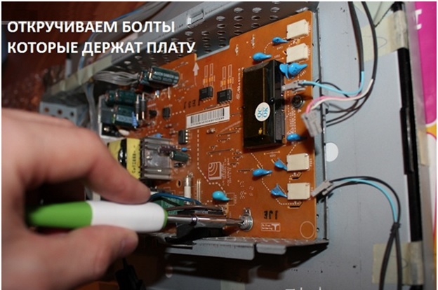
Disassemble the monitor or TV. After removing the plastic case, carefully disconnect the wires from the board, remove the metal frame from the LCD module and remove the matrix. You need to be especially careful with the matrix so as not to damage the fragile connecting cables. If everything is done correctly, then full access to the electronic board, power inverter and backlight elements will be open.


2. Disconnect the pencil cases from lamps from the matrix or the lamps themselves, if they are installed without canisters.

3. Disconnect old lamps and recycle them. With elements CCFL You also need to be extremely careful, because they contain mercury.
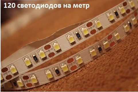
4. We proceed to the replacement stage. First you need to purchase an LED strip, preferably with a reserve so that it is enough to replace all the lamps (measure the length of the lamp and multiply by their number). It should be as narrow as possible and have at least 120 LEDs per meter. To make the backlight more pleasing to the eye, it is better to take LEDs with a white glow.
5. The strip with LEDs must be glued with double-sided tape to where the lamps were. Next, wires from old lamps are soldered onto the contact terminals of the strips and insulated with hot-melt adhesive. You can immediately check the functionality of this design by connecting the wires to an external power source.


6. Now you need to connect the backlight to the power board of the monitor or TV. To do this, you need to find jumpers marked “12 V” and solder the backlight wires there, observing the polarity accordingly. Reassemble the monitor in reverse order and enjoy your invention.

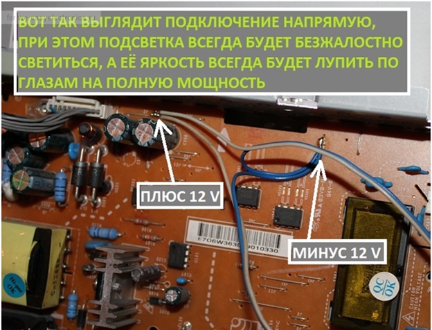
Backlight in this case it will work when the device is connected to the network.
To control the backlight and bring it into normal mode, you will have to work hard. The wires leading to the LEDs must be powered in such a way that it is possible to turn on the backlight when you press the on/off buttons and adjust its brightness. There are 2 options for this:
1.We independently create a power supply circuit and adjust the backlight brightness:
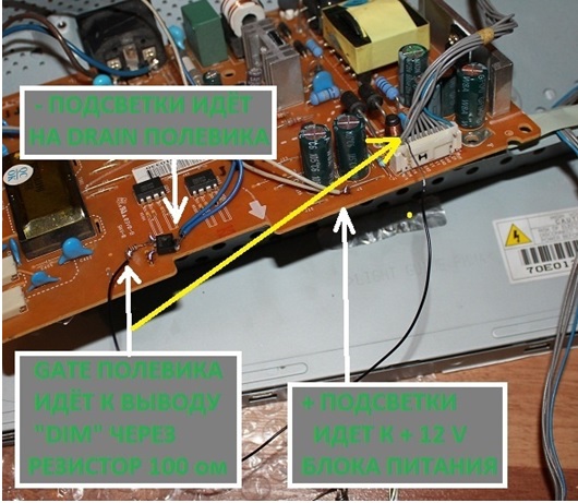
On the monitor or TV power chip we look for a plastic box (connector) with wires coming out of it, where each socket is labeled on the board.

Here we are interested in the “DIM” output. It will be responsible for sending a signal to turn it on/off and adjust the brightness by changing the duty cycle in the PWM controller. The duty cycle of the pulses changes until the desired brightness level is established, and the limit values will correspond to turning on and off.
Now we need an N-channel field-effect transistor(field worker) anyone. Wires from the LED strip with a minus are soldered to its drain (Drain), the common wire from the backlight is also connected to the source (source), and the gate (gate) is connected through a 100-200 Ohm resistor and any wire is connected to the “DIM” terminal.
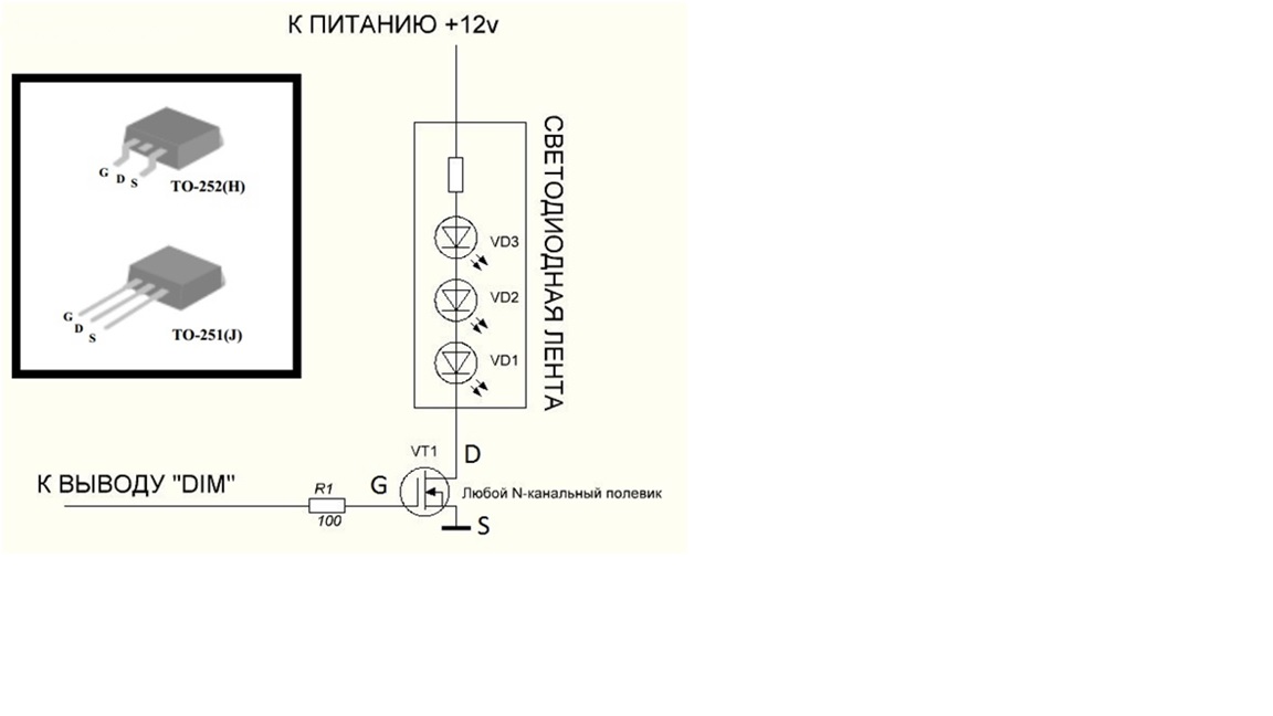
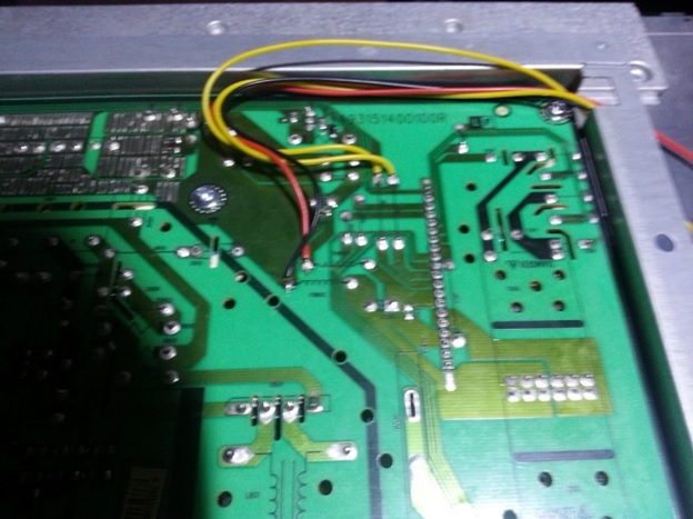
We still have wires from the backlight with a plus, we bring them to the +12V power supply on the microcircuit and solder them.

Now we install the backlight in its rightful place and assemble the monitor in reverse order. Do not forget about caution and accuracy when handling the matrix and filters so that dust does not get in and the cables are not damaged. That's it, you can use it.


The second way, more expensive but convenient, is to buy a ready-made LED backlight with your own inverter :
Again, pay attention to the plastic connector and DIM pin (brightness) and the on/of pin (it’s better to use the pinout).

Using a multimeter, we determine the places on the control unit of old lamps from which the signal for brightness and on/of comes.
Now solder the wires to the found places inverter new LED backlight .
Also, it is better to unsolder the jumpers from the inverter power supply of the old lamps so that the backlight can be regulated by the new inverter.