Checking the monitor inverter without a lamp. How to repair or repair an LCD and LCD TV yourself if its inverter is broken. The main malfunctions of inverters in modern LCD and plasma TVs, as well as ways to eliminate them at home
In this material, the author continues the topic started in the article - he describes in detail the diagnostics of power inverters for cold cathode electroluminescent lamps (CCFL lamps). Fundamental electrical circuits All inverters discussed in the article are given in.
Correct fault diagnosis significantly reduces repair time and costs. The main problem that arises when diagnosing a backlight system is to determine what is faulty: the backlight lamp or the inverter. Practice shows that the malfunction of CCFL lamps manifests itself as follows:
The screen turns red;
When you turn on the laptop, the screen color has a red tint, and then gradually becomes normal;
The panel backlight (the entire image) blinks in time with the changing brightness of the scene;
The panel backlight begins to blink and then turns off.
The malfunction of the lamps with such manifestations is confirmed in approximately half of the cases; in other cases, it is necessary to refer to the methods outlined below.
Structurally, the inverter board and backlight lamps are usually located under the front cover of the laptop screen. The first thing to check is whether the backlight problems are related to a malfunction of the laptop motherboard. If, when connecting external display devices - a monitor, TV, projector, there is an image, then most likely the laptop's backlight system is faulty.
To repair an inverter or lighting system, you must have the minimum necessary measuring equipment at your workplace - a multimeter, an oscilloscope and an autonomous power supply with an adjustable constant voltage from 1.5 to 30 V with current protection (1 A), as well as a working CCFL lamp.
To eliminate the influence of a faulty lamp, an equivalent load is used when repairing the inverter. It is preferable to connect a known good lamp to the inverter being tested. If there is none, then a resistor with a nominal value of 100...130 kOhm and a power of 2...5 W is connected to the output connector of the inverter (as recommended by inverter manufacturers). The resistor is selected based on the required secondary output voltage feedback. A ceramic capacitor with a capacity of 20...200 pF and an operating voltage of at least 2 kV can also be used as an equivalent load. Using a capacitor when testing the inverter in operating mode is preferable, however, problems may arise when starting the inverter controller. The inverter can be considered operational if there is a stable sinusoidal voltage at the load equivalent.
Replacing a lamp requires special care and ensuring the cleanliness of the room. Work is carried out with gloves. In some cases, when complete disassembly of the matrix is required, this operation is carried out in “clean” rooms and in special clothing.
Backlight malfunctions are sometimes associated with poor contact at the welding (soldering) site of the inverter wire and the lamp electrode. In this case, it is possible to restore the functionality of the backlight system. To do this, you must have an insulating tube (rubber tip) from a faulty CCFL lamp. It is better to do welding or soldering with hard solder and a gas soldering iron, which creates high temperature at the soldering point. The tube, previously placed on the wire, is carefully pulled onto the soldering site and the lamp is ready for use.
Malfunctions and repair of SAMSUNG laptop inverter
To access the inverter board and lamp, remove the decorative cover from the LCD panel of the laptop, disconnect the cable connecting it to the motherboard and the lamp connection cable from the inverter.
The screen does not light up
Check the serviceability of the inverter elements by external inspection. In this case, the malfunction of the power elements and, first of all, the transformer, is determined by the darkening of its body, burnt insulation, darkening and even destruction of the board underneath.
Check the presence of voltages at connector CN1 (Fig. 3c): +12 V on pins 1-2, inverter turn-off voltage on pin 4 and brightness voltage on pin 3.
In normal mode, when loading video card drivers, there should be no voltage on pin 4 of CN1. The inverter turns on automatically when supply voltage is applied. The brightness voltage (pin 3) must be at least 0.5...2 V.
Check the voltage at the emitter of transistor Q4, and if it is missing, check fuses F1, TF1, as well as transistors Q7 and Q5.
Check the serviceability of transistors Q1, Q2. These are digital transistors of the KST1623 type, they are produced in an L4 package, they can be replaced with an analogue of the BSS67R type. If transistor Q1 fails, it is enough to replace only it. If transistor Q2 fails, check the serviceability of transistor Q7 and operational amplifier U1A.
If fuse F1 is good and TF1 (self-resetting fuse) is faulty, then before replacing it, check the serviceability of transistor Q4 and zener diode D2.
Check the brightness control voltage on pin 3 of CN1. For diagnostics, pin 3 is supplied with a voltage of about 3 V from an external source. If the screen lights up, then the cause of the problem is the laptop's motherboard. In this case, you can force turn on the screen backlight by applying voltage from a resistor divider (80 kOhm in the upper arm (to +5 V), and 40 kOhm in the lower arm) connected to the +5 V bus. If the screen does not light up, check the serviceability of transistor Q8 .
The backlight turns off 1-2 seconds after the start of loading operating system
First of all, check the serviceability of CCFL lamps. Connect the oscilloscope to pin 1 of connector CN2 (see Fig. 3c) and an equivalent load. If there is a sinusoidal voltage with an amplitude of 500...700 V and a frequency of 60...70 kHz at this ("hot") contact of connector CN1, then the inverter is working and turning off the backlight may be due to a malfunction of the lamp or poor contact between the inverter wire and the electrode lamps. All this requires disassembling the laptop and removing the lamp. Observe the shape and voltage level at an equivalent load for at least 10 minutes, and replace the faulty lamp. If there is no voltage or its waveform is significantly distorted, then the malfunction is due to internal problems in the inverter.
Check the feedback circuit. If, when the inverter is turned on, an oscilloscope registers any signal at the “cold” contact of the lamp (its shape does not matter) with an amplitude of at least 1.5 V, and on the pin. 6 U1 voltage remains unchanged ( constant pressure, which is measured with a multimeter), check the serviceability of diode assemblies D4, D5 (they can be replaced with any suitable size, or with two separate diodes of the BAV99 type in SMD cases). If assemblies D4, D5 and resistor R14 (1 kOhm) are working, then the U1 chip is faulty.
Check the precision stabilizer U2 (TL341). If it is working, then on the pin. 5 U1 should be constant voltage 1.5V. In addition, this inverter protection line is connected with brightness control and overload protection circuit. To determine which of these circuits is faulty, turn them off sequentially (but not simultaneously) for a while. First, the protection circuit D3 R3 R4 is turned off, then the brightness control circuit - transistor Q8. If, when these circuits are disconnected, the lamps work stably, then the fault is in these circuits.
Check the presence of contact in connector CN2. In case of visible burning of the contact, it is restored. If the contact does not cause suspicion, connect an equivalent load. Check the overload protection signal generation circuit D3 C3 C4 D5. The protection may be triggered due to overheating of transformer T1, malfunction (leakage) of transistors Q5, Q6.
Malfunctions and repair of inverter based on MP1101 controller
The screen does not light up
Check for voltage on pins 4 (VCC), 2 (Enable) of connector JP1 (Fig. 4c). In this case, the supply voltage should be 12 V, the Enable inverter switching voltage should be at least 1.5 V. The absence of Enable voltage indicates a malfunction of the laptop motherboard, most likely the video card. The absence of 12 V voltage at the JP1 connector when the cable connecting the inverter to the motherboard is disconnected indicates a malfunction of the motherboard. If there is 12 V voltage at the connector, and at the pin. 6 U1 it is equal to zero, then check the serviceability of the filter capacitors, fuse F1 and controller U1.
Check the inverter switch-on voltage at the pin. 4 U1. If it is missing, check its presence on the contact of the connector disconnected from the inverter board. If there is no voltage, check the laptop circuit. The absence of an inverter switch-on voltage can be associated either with a malfunction of U1 or with a break or “cold” soldering of the resistor REN1 (there are no radio element designations on the inverter board based on the MP1011 controller, so refer to Fig. 4c). To eliminate this problem, simply solder the SMD resistor REN1. Check the serviceability of transformer T1 (see above), CON2 connector and wires.
The backlight turns on for 1-2 seconds and goes off
First of all, check the elements of the feedback circuit D2 (a, b) CSENSE RSENSE. Diodes are checked for open circuit or breakdown. Check the serviceability of the lamp (see above). Connect an equivalent load. Connect the oscilloscope to the Lamp+ circuit (Fig. 4c). If, after the operating system starts loading, a sinusoidal voltage of 500...700 V is present at this pin, then the main inverter board is working and the lamp needs to be replaced.
The reason for the backlight to disappear may be a malfunction of the feedback unit. If when you turn on the screen on the pin. 2, a positive voltage of about 0.5 V appears for a while, but the lamps go out, then the MP1011 controller should be replaced. If the feedback voltage is less than 0.1 V, check all elements in the feedback circuit: D2, RSENSE, CSENSE.
If, when the inverter is turned on, a signal with an amplitude of more than 0.5 V is recorded on the “cold” terminal of the lamp by an oscilloscope, and on the pin. 2 U1 voltage remains unchanged (constant voltage, which can be measured with a multimeter), then check the serviceability of the diode assembly D2, it can be replaced with two diodes of the BAV99 type. If the diodes are working and the RSENSE resistor (140 Ohm) is not broken (cold soldering), then the MP1011 controller is faulty.
Backlight turns off after a few seconds or minutes
In this case, check the T1 transformer, the CSER capacitor (for leakage) and the lamp connection wires for possible insulation damage and contact with metal objects of the housing.
Malfunctions of inverters based on the OZ9938 controller
The screen does not light up
Check the serviceability of fuse F1 (Fig. 5c). If it is faulty, then before replacing it, check the serviceability of transformer T1 according to external signs(darkening, burnt insulation, board burnout). Then check the breakdown of the transistor assembly of field-effect transistors U1. If the OZ9938 controller is powered by a separate parametric stabilizer (not shown in the diagram), check the serviceability of its elements.
If the inverter circuit is working properly and there is a sinusoidal voltage of 550 V with a frequency of 55 kHz at pin 7 of transformer T1, then check the serviceability of the SG connector.
Check for the presence of switching voltage (at least 1 V) on pin 6 of connector CN2. If the voltage is below normal, the pin is unsoldered. 10 controllers from the ENA bus. If the voltage at pin 6 increases to 2 V, check capacitor C18 or replace controller U2. If the voltage on pin 6 remains low, the reason is in the laptop motherboard. You can get out of this situation by applying a voltage of 2 V from an external source.
Check the voltage at the pin. 4 U2, if it is less than 0.1 V, then check the controller, laptop board and capacitor C10. Check the voltage at the pin. 11 U2, which in normal mode should be more than 3 V, with undervoltage C14 is checked at this pin, resistor R9 is soldered. If the specified elements are serviceable, then replace the controller. The backlight turns on for 1-2 seconds and goes off
This defect may be due to a malfunction of the lamp and its connection circuit. If the lamp is working, then check the feedback circuit D1 C22. If, in the absence of a signal to turn on the inverter, the voltage at pin 6 of U2 is more than 1 V, then this microcircuit is faulty and must be replaced. If the voltage at the pin. 6 less than 0.7 V, the lamp is working, and the backlight turns off within a few seconds, check the overload protection circuit D2 R5 R3. If the voltage at the pin. 6 when the inverter is turned on, increases and at one moment exceeds the voltage of 3 V and at the same time the lamps turn off, then the reason is the overload of the inverter output stage. This may be caused by a faulty lamp (start-up problems when the lamp takes a long time to start-up). In addition, overload may be due primarily to the presence of short-circuited turns of the transformer windings.
If the voltage at the pin. 6 does not exceed 3 V, but the lamp turns off, then check for a voltage of no more than 3 V on the pin. 7 U2. If the voltage is below this level, then check capacitor C8 (leakage) or replace controller U2.
The backlight turns off a few minutes after turning it on
Check the overload protection circuits D2 C2 C5. Check the serviceability of transformer T1 (see above). Sometimes the malfunction appears after some time, during which the transformer heats up (above 50°C), then it is necessary to replace it. Check the serviceability of the transistor assembly U1 (can be determined by its operating temperature). As a rule, this malfunction disappears while the suspicious elements are “frozen” with Freeze gel. If the time after which the backlight turns off is unstable, then check the serviceability of the lamp and its connector.
Malfunctions of inverters based on the OZ960 controller
The screen does not light up
For inverters such as AMBIT and KUBNKM (see Fig. 6 c) this may be accompanied by a lack of indication on the front panel. In this case, disassemble the laptop and check for +12 V voltage (for KUBNKM inverters the input connector J1 (CN1) is 20-pin, the supply voltage is supplied to the 4 outermost pins, and for AMBIT inverters the connector is 16-pin, and the supply voltage is supplied to the 2 outermost pins contact). If fuse F1 is faulty, check transistor assemblies U1, U3. Check the presence of supply voltage at the pin. 5 OZ960 controllers (U2). This tension, unlike standard scheme inverter (Fig. 6c), comes from pin 1 of J1 through the stabilizer on transistor Q1 (designation on the board). In AMBIT inverters, controller U2 is powered from pin 4 of J1. There may be no supply voltage at the connector itself due to a faulty laptop power supply or due to a short circuit to ground at the pin. 5 U2. For diagnostics, disconnect the SVDC line from connector J1 and, if voltage appears on the bus, then the inverter is faulty.
Check the presence of the ENA controller turn-on voltage on the pin. 3 U2, it must be at least 2 V. In the KUBNKM inverter, the controller turn-on voltage comes from transistor Q1 (its supply voltage is also removed from it) but through a 10 kOhm resistor. Other modifications of inverters based on the OZ960 controller may also have their own characteristics and differences from the standard circuit, but the troubleshooting technique for them is the same.
If the LEDs on the laptop keyboard panel are lit, there is no screen backlight, and the voltages listed above are present, then check the serviceability of field-effect transistor assemblies U1, U3, as well as zener diodes D1, D2 (4.7 V).
When you turn on the laptop, use an oscilloscope to monitor the presence of rectangular pulses on the pin. 11-12 and 19-20 U2. If there are no pulses and the U1, U3 assemblies are working properly, then check for the presence of a voltage of 2.5 V on the pin. 7 U2. If it is missing or it is underestimated, check C13 and replace the controller. Check for the presence of a sinusoidal signal at the pin. 18 U2 with a frequency of 50.60 kHz. If the frequency differs significantly from the nominal one or there is no signal at all, check elements C5, R4.
The lack of backlight may be due to the lack of (low) voltage at the pin. 14 controllers. If the voltage at this pin is less than 1 V, apply 3 V from an external source. If the screen lights up, then the problem is related to the brightness control voltage supplied from the laptop board. In this case, you can apply voltage from pin 1 of J1 to the brightness control input through a resistive divider, but it must be taken into account that the brightness will not be adjusted
The backlight turns off 1-2 seconds after turning on the laptop
Make sure that the backlight lamp is working properly (see the verification method above). They are connected with an oscilloscope to the “hot” (upper in the diagram in Fig. 6c) output of transformer T1. If, when you turn on the laptop, a sinusoidal voltage with a frequency of 55...60 kHz appears at this pin and immediately disappears, check the serviceability of transformer T1. Then they check the serviceability of the transistor assemblies U1, U2 for leakage: measure the resistance between source and drain with an ohmmeter, and if it shows the final value at the limit of 100 kOhm, then replace the assembly. Check the serviceability of capacitor C4 for leakage (ESR).
Check the presence of feedback voltage at the pin. 8 of the controller, it must exceed 1.25 V. If the voltage is below this value, check the diode assembly CR1, and also solder resistor R8. If there is no result, replace the U2 controller.
Backlight turns off after a few seconds or minutes
In this case, check the surge protection circuit. Disconnect it from the main circuit (just unsolder the CR2 diode assembly). When you turn on the laptop, check for voltage at the pin. 2 controllers (should be no more than 1 V). If this voltage exceeds the specified level, check the threshold value of 2.5 V at the pin. 7. If it is missing or the voltage is too low, replace the controller. If the voltage at the pin. 2 is normal, but when connecting the protection circuit, the voltage becomes higher than 2 V or changes over time, check the serviceability of the transformer, capacitors C7, C11, diode assembly CR2. You can replace the transformer with any type from another inverter (this circuit is insensitive to the type of transformer), the only thing that will need to be adjusted is the feedback voltage coming from the cold end of the lamp (by selecting resistor R8).
In an AMBIT type inverter, which uses an OZ979 chip to power the keyboard LEDs, you can try to restore the screen backlight using a temporary scheme. The lamps are turned off and lines of LEDs are fixed (glued) on the back side of the LCD matrix at the top and bottom of the screen, 3 pieces each. in 5 lines, the first LED is connected to pin 3 of the OZ979, and the last one is connected to the housing. This method is suitable for small screens of 10-12 inches.
You can use an inverter circuit based on OZ960; after the transformer, instead of capacitor C4, a double diode in an SMD package and a quenching resistor with a nominal value of 50 Ohms are installed. The resistance is more accurately selected when installing LEDs to ensure normal illumination and, depending on their operating current, for normal illumination of a 15-inch display, 16 ultra-bright LEDs, for example FYLS-1206W white, are sufficient. LEDs can be glued to fluoroplastic tape and connected with thin conductors. In this case, the input voltage on the first LED should not exceed 80 V at a current of 25-50 mA. The current through the LEDs is set by selecting the value of the limiting resistor.
Some circuits based on OZ960 differ from the standard one, including the name and location of some electronic components.
Sometimes there is a decrease in the brightness of the backlight and its adjustment is not enough. This occurs due to a decrease in the current of the gas-discharge lamp due to an increase in the transition resistance at the contact point on the board of the high-voltage winding of the transformer T1 and the ballast capacitor C4. The problem is eliminated by soldering the capacitor leads.
Literature
1. Vladimir Petrov. Repair and maintenance of power inverters for backlight lamps of LCD panels of laptops. Repair & Service, 2010, No. 3, p. 37-40.
Hi all!
In this article we will explain to you what it is , what significance does it have in lcd panels and how it works.
An inverter is a converter of direct voltage (usually 12V) into high-voltage alternating voltage.
In order for the LCD panel to provide a bright image, a light flux is needed, which is passed through the matrix and, in fact, forms the image on the screen. IN LCD monitors to create such luminous flux fluorescent lamps are used lamps backlight cold cathode (CCFL). In monitors, these lamps are usually located along the edges (top and bottom), and in TVs, directly under the matrix throughout the entire area. Using filters and a diffuser, the lamps evenly illuminate the entire surface of the matrix. In order to ensure the starting or “ignition” of lamps with a voltage of more than 1500V, and then powering these lamps for a long time in operating mode with a voltage of 600...1000V, inverters are used.
In LCD monitors, lamps are connected using a capacitive circuit.
The inverter provides the following functions:
converts direct voltage into high-voltage alternating voltage;
stabilizes and regulates the lamp current;
provides brightness adjustment;
ensures coordinated operation of the inverter output stage with the input resistance of the lamp;
creates protection against overloads and short circuits.
Structural
As shown in the diagram, the standby mode unit, as well as the inverter switching on, is made on keys Q1 and Q2. Since the monitor takes a little time to turn on, the inverter turns on 2...4 seconds after the monitor is switched to operating mode. When voltage is ON. (on/off), the inverter enters operating mode. This unit also turns off the inverter if the monitor goes into saving mode.
When the switch base Q1 receives positive voltage ON. (3…5V), +12V voltage is supplied to the brightness control unit and the PWM regulator.
The unit for monitoring and controlling the brightness of lamps and PWM (3) is made according to the circuit of an error amplifier (EA) and a PWM pulse shaper. This node receives the dimmer voltage from the main monitor board, then this voltage is compared with the feedback voltage, and then an error signal is generated that controls the frequency of the PWM pulses. These pulses control the DC/DC converter (1) and synchronize the operation of the converter-inverter. The amplitude of the pulses is constant and is determined by the supply voltage (+12V), and the frequency of the pulses depends on the brightness voltage and the threshold voltage level.
Thanks to the DC/DC converter, a constant (high) voltage is supplied to the autogenerator, which is turned on and controlled by PWM pulses of the control unit (3).
The level of the inverter's AC output voltage depends on the parameters of the circuit components, and its frequency is determined by the brightness control and the characteristics of the backlight lamps. The inverter converter is usually a self-excited generator. The circuits can be used as single-cycle or push-pull.
The protection unit (5 and 6) analyzes the level of current or voltage at the inverter output and generates feedback and overload voltages, which are supplied to the control unit (2) and PWM (3). If the value of one of these voltages exceeds the threshold value (short circuit, converter overload, undervoltage), the oscillator stops operating.
Typically, the control node, PWM and brightness control node are combined in one chip. The converter is made on discrete elements with a load in the form of a pulse transformer, the additional winding of which is used to switch the trigger voltage.
All main inverter components are housed in SMD component housings.
There are a huge number of modifications of inverters.
The inverter in a TV is a device for starting and stable operation of fluorescent lamps for the backlight of an LCD panel. Ensures the constant glow of these light sources for a long time and effectively controls their brightness. It can be made in the form of one or two separate blocks (master/slave), and also located together with the power supply on a single board. If you do it yourself, you need to know the functions it performs.
Tasks of the television inverter:
- conversion of direct voltage 12 - 24 volts into high-voltage alternating voltage
- stabilization and adjustment of lamp current
- backlight brightness adjustment
- providing protection against overloads and short circuits
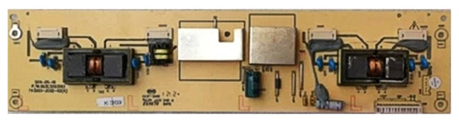
Electrical circuit of a simple inverter for 2 backlight lamps
 The device is implemented on a PWM controller U1 (OZ960), two assemblies of field-effect transistor switches (u1, u2) and high-voltage transformers T1, T2. Through connector CN1, 12 volt power (F1), a power command (ON/OFF), and constant voltage (Dimm) are supplied to adjust the brightness. The protection unit (D2, D4, D5, D6) analyzes the current or voltage at the output of the device and generates overload and feedback voltages (OS) supplied to the PWM. If one of these voltages exceeds the threshold value, the oscillator at U1 is blocked, and the inverter will be in a protection state. The node is blocked when the supply voltage is low, when the supply voltage “drops” when the load is turned on, when the converter is overloaded or there is a short circuit.
Characteristic signs of inverter malfunction
- Backlights do not turn on
- The backlights turn on a short time and turn off
- Unstable brightness and screen flickering
- The inverter periodically does not turn on after a long period of inactivity
- Uneven screen illumination with a 2-inverter circuit
Features of inverter unit repair
 When diagnosing faults related to the correct operation of the inverter, you should first of all make sure that there is no ripple in the supply voltage and that it is stable. Pay attention to the passage of startup commands and backlight brightness control from the motherboard. Eliminate the influence of backlight lamps by using their equivalent in cases where the problem is not clear. Take advantage of the opportunity to remove protection from the inverter during repairs to determine the defective part. Do not forget about a careful visual inspection of the board and what every professional TV technician uses when repairing TVs at home - measuring voltage, resistance, capacitance using special instruments or a tester.
Sometimes, upon careful inspection of the board, you can see “burnt out” parts that need to be replaced. Very often field-effect transistor switches fail, but sometimes replacing them does not always lead to a positive result. The functionality of the unit may be restored for an indefinite period of time, and then the malfunction may occur again. You have eliminated the effect, but not the cause. Therefore, without knowing the intricacies of repairing these devices, you can lose a lot of time and effort to restore them. And, if you have doubts about the success of the matter, call a technician who has already repaired similar devices many times and knows all the “pitfalls and shoals” thanks to his accumulated experience and professional knowledge.
![]() High-voltage transformers are considered the weak link in the inverter units. Working in conditions high voltage requires special assembly quality of these components and places high demands on insulation properties. In addition, it should be said that transformers can become noticeably heated during the operation of the backlight. Defects such as a break or inter-turn short circuit of the windings of these parts are commonplace. Diagnostics of these elements can be complicated by the fact that a short circuit or break can only be observed in operating mode, and “diagnosis” of them in a de-energized state will not reveal problems with them. Here, swapping the dubious and serviceable transformer and further analyzing the situation can come to the rescue.
High-voltage transformers are considered the weak link in the inverter units. Working in conditions high voltage requires special assembly quality of these components and places high demands on insulation properties. In addition, it should be said that transformers can become noticeably heated during the operation of the backlight. Defects such as a break or inter-turn short circuit of the windings of these parts are commonplace. Diagnostics of these elements can be complicated by the fact that a short circuit or break can only be observed in operating mode, and “diagnosis” of them in a de-energized state will not reveal problems with them. Here, swapping the dubious and serviceable transformer and further analyzing the situation can come to the rescue.
 Different TVs use inverters with different numbers of transformers. In small-sized devices, the inverter can contain 2 - 4 transformers; in large-diagonal TVs, especially of previous years of production, there were up to 20 similar products. Naturally, a large number of them reduces the reliability of the circuit as a whole, so in modern models their use is minimized due to innovative technical solutions.
A sign of an inverter malfunction in most cases is the absence of an image on the TV screen when there is sound. However, situations are possible when the TV, after trying to turn on, goes back into standby mode or starts flashing the LEDs on the front panel, and in this case no sound appears. The nature of the defect is different, and the source may still be the same inverter unit. Some TV models contain a feedback signal from the inverter to the motherboard processor, indicating malfunctions in its operation. Without receiving confirmation from the inverter that everything is fine with it, the processor changes the TV’s operating mode to standby or displays error messages through LED indicators. For some manufacturers, after a certain number of unsuccessful starts, the system may stop sending a command to turn on the backlight until errors are reset or the memory is cleared.
 The inverter is a complex electronic device, do-it-yourself repair which may cause certain difficulties. These blocks for TVs with diagonals from 26 inches and above are “tied” to a specific LCD panel and, according to manufacturers, are a single device (together with the T-con block). It is very rare to find electronic circuits for these products, and never for a matrix controller. Therefore, even a professional, when diagnosing this equipment, has to recall the experience of repairing similar devices, be guided by the general principles of their circuit design solutions and use the database of datasheets for backlight driver microcircuits and key transistors. If you decide to repair the inverter yourself, but something goes wrong,
As you know, modern LCD monitors work to “transmit” light - a translucent picture on the matrix is illuminated from behind, the light passing through the matrix and its light filters forms an image. A fairly bright source is used as backlight white light– the light transmission matrix is more reminiscent of rather dark sunglasses.
Traditionally, cold cathode fluorescent lamps, or CCFL – Cold Cathode Fluorescent Lamps, have been used for this. These lamps are glass tubes with a diameter of 2-3 mm, the inner surface of which is coated with phosphor. The tubes are filled with mercury vapor. When an electric discharge passes through the gas, radiation is generated, causing the phosphor to glow. To operate such a lamp, a high alternating voltage is required - about 1500 V with a frequency of about 40-50 kHz.
Among the most common malfunctions of liquid crystal panels is the failure of the backlight or inverter - a device that converts direct voltage (usually 12-18 V, depending on the monitor's power supply) into alternating voltage to operate the lamp. This manifests itself in a sharp decrease in the brightness of the screen, usually from one of the edges, or in the complete shutdown of the backlight - in this case, the image on the screen is barely visible.
In branded services, such faults are “cured” by replacing the entire panel, especially in the case of laptop panels. It’s quite expensive, but in the case of a monitor, it’s easier to buy a new one. Fortunately, there are not only branded services in the world, but also a considerable number of “craftsmen” who have mastered the operation of replacing backlight lamps or inverters.
Replacing the backlight lamp is a simple operation, which is provided “structurally” in some monitors. If anyone hasn’t read Igor Pichugin on RadioKot, I’ll give a short “squeeze” from it.
The lamps are mounted along one side of the display in a “pencil case”. Typically, removing the pencil case requires disassembling the LCD panel, that is, removing the metal casing and the panel itself. A thin (about 0.5-1 mm) control board is mounted behind the panel, connected to the matrix itself with several cables. To remove the liquid crystal screen, you must carefully peel off (do not cut under any circumstances! Damaged data lines on flexible cables cannot be restored) the protective film.
To demonstrate “classic” backlight technology, I use an LG Flatron L1970H LCD monitor.
Let's start disassembling the monitor by removing the stand. You need to remove the plastic casing from the back that covers the backlight mount and the cables from the connectors on the stand.
After removing the stand, remove the LCD module from the case. The front frame is secured with latches and can be easily separated from the rear of the case.
The LCD module is covered with a metal casing. Through the holes in it, inverter transformers with menacing inscriptions are visible.
Unscrew the screws securing the casing.
Now you can see in detail the monitor’s control electronics board and the inverter, which is made as a separate unit.
The electronics board is connected by a separate harness to the LCD matrix decoder, covered with a thin self-adhesive film.
The decoder is connected to the matrix using thin flexible cables. If you have to remove the panel, carefully peel off the protective film - the flexible data lines cannot be restored, in which case the matrix will have to be thrown away.
The inverter mounted behind the monitor can often be replaced with a similar one. It is enough to know the supply voltage and the number of lamps. In addition, the inverter in monitors is usually large and repairable.
The lamps will be connected to the inverter using standard connectors.
In this monitor, the lamp cases can be removed without disassembling the panel. You just need to unscrew the screw...
...and pull out the pencil case.
The lamps are mounted in canisters of two. A sign of an “old” lamp is black rings around the cathodes. In burnt-out lamps they are much wider and darker.
It was no coincidence that I needed lamps. They brought a battered Fujitsu-Siemens Amilo M7800 laptop to “look at” with a diagnosis of “very dark image on the screen.” The company service asked for some unrealistic money for repairs - apparently they were going to change the matrix. I had just read an article on “cat” and was going to try to change the lamp.
To access the LCD panel, the first step is to remove its frame. Usually it is secured with latches, but some laptop models may also have screws hidden under rubber plugs.
At the bottom of the laptop's LCD screen, between the hinges, is the inverter in a protective casing.
It makes sense to check whether the lamp is really faulty, or whether the inverter has failed. To do this, just connect a known-good lamp to the inverter.
Laptop inverters are quite miniature and in case of malfunction they are usually replaced entirely. Replacement with a similar one from another model is acceptable, since they are available both at radio flea markets and at Dealextreme.
When replacing an inverter, it is advisable to determine how the on/off and backlight brightness are controlled. Typically, for this purpose, the cable going to the inverter contains DIM signals (brightness control, usually varying from 1 V - the lowest brightness to 3 V - the highest) and ENABLE (0 V - backlight off, 3 V - backlight on). Usually they correct connection not necessary for the operation of the new inverter, but allows you to retain some energy saving features.
To replace the lamp we will need to remove the LCD panel. You need to unscrew the screws that secure it to the hinges and lid of the laptop.
There are metal guides on the sides of the panel that must be removed for further disassembly.
In the panel used in this laptop, you can get to the lamp without disassembling the entire panel. You just need to remove one side of the metal frame and open the plastic case.
It would seem that the next step is obvious - we go to the radio market, buy the necessary lamp and put it in the laptop. The reality turned out to be somewhat more complicated. On Mitino there were no lamps of suitable length; they were either very short (15 mm shorter) or very long (15 mm longer). In the stall of the Istok-2 company (this is a stall with radio tubes and all sorts of lighting equipment, located at the end of the basement floor farthest from the entrance, it glows like Christmas tree) advised to use a line of super-bright LEDs.
The width of such a ruler is about 3 mm. The diodes on it are installed in groups of 3 pieces, each about 15 mm long. Accordingly, you can cut the ruler to the required length with acceptable accuracy.
Now, with the development of technologies for manufacturing high-power LEDs white glow, LED backlighting began to be installed in some LCD monitors and televisions. In fact, anyone can join the “leading edge” of technology by installing such lighting to replace the burnt-out “lamp” one. Yielding to the persuasion of the “originists,” I bought a ruler 300 mm long for 250 rubles (approximately the cost of the lamp).
The LED line fits wonderfully inside a standard pencil case.
For check LED backlight It is enough to connect the ruler inserted into the matrix to a suitable power source. When turned off, the screen should glow milky white.
Reassemble in reverse order (c).
Instead of an inverter thrown out as unnecessary, you can assemble a circuit like this:
We select resistor values depending on the parameters of the DIM and ENABLE signals and the supply voltage.
In conclusion, I want to say a few words about why LED backlighting is disgusting.
Firstly, the emission spectrum of LEDs does not quite match the spectrum of lamps. Therefore, on monitors designed for working with graphics, such a replacement can only do harm.
Secondly, sometimes there are “smart” inverters controlled by digital signals (usually via the I2C bus, but there are also more exotic ones). If there is no inverter, the LCD panel may not turn on.
Thirdly, the main disadvantage of LED backlighting assembled “on the knee” is some unevenness of the glow near the lamp.
It is noticeable in the photo that the illumination of the lower part of the screen is not very uniform, and the lower right corner is generally dark; unfortunately, the ruler turned out to be a little short.
In any case, replacing the CCFL lamp with LEDs is an affordable and inexpensive way to restore LCD monitors. The existing shortcomings cannot be called critical, but in the case of lamps of non-standard sizes, like mine, this is quite justified.
The entry was published on the blog of Shura Lyuberetsky. You can leave your comments there using your LiveJournal username (OpenID login).
For a good image on an LCD TV, the matrix must have good lighting. In LCD TVs, the backlight is provided by a voltage inverter made using lamps, LEDs, or more advanced OLED (organic light-emitting diode-based) backlighting. The backlight should provide uniform illumination of the entire surface of the matrix, sufficient brightness, and a quick response to changes in signal brightness.
The most common sign of a faulty inverter is the absence of a picture when there is sound. Although another option is possible, when the TV tries to turn on, but goes into standby mode again and the sound does not appear.
It is impossible to describe all possible malfunctions of inverters, so in this article I will give the main ones, by understanding the essence of which you will be able to repair LCD TV voltage inverters with your own hands.
Here are some signs that the inverter is faulty:
- The backlight does not turn on;
- The backlight turns on and off immediately;
- Does not turn on after a long period of inactivity;
- Screen brightness flashing;
- Uneven screen brightness.
But first, let's look at their structure.
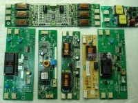
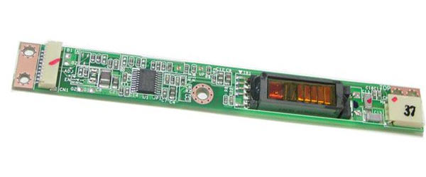
LCD TV inverter board for 4 lamps
The inverter device can be divided into functional blocks, from which it becomes clear that they are all similar to each other.
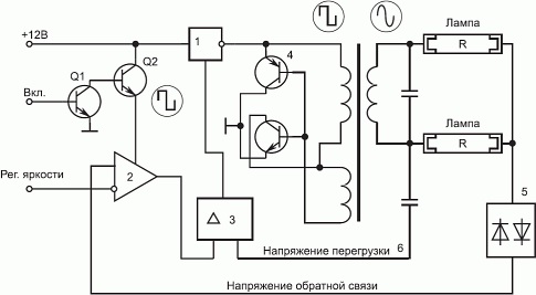
Below circuit diagram inverter belongs to lamp lighting. The lamps are connected using a capacitive circuit, which ensures their constant glow over time and provides effective brightness control. Transistors Q1, Q2 – turn on and turn on the inverter.
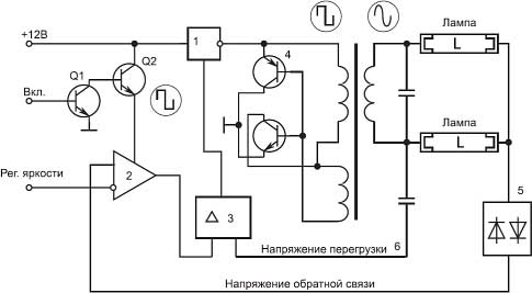
Inverter circuit diagram
Block (1) provides constant voltage to the autogenerator with keys ((4) usually consists of two field effect transistor, such as APM4010 and APM4015), which is turned on and controlled by PWM signals. The brightness control unit (2) and PWM (3) are usually constructed in one chip. A pulse-width modulator (PWM) controls the load in the secondary circuits and, if the lamps malfunction, does not allow the autogenerator 4 to turn on, which will protect against failure of the keys or transformer.
The required luminous flux is created fluorescent lamps(R) cold cathode (CCFL) are located behind the matrix and illuminate it evenly.
PRINCIPLE OF OPERATION
The inverter must provide several functions:
- Change direct voltage into high-voltage alternating voltage;
- Provide brightness adjustment;
- Stabilize the lamp current and regulate it;
- Provide protection against short circuit and overload.
The matrix backlight inverter (for lamps) should provide a voltage of usually 600 volts with a load current of approximately 10 mA and provide a maximum screen brightness of about 250 cd/m2. In this case, the initial output voltage will be about 1600 V, and the protection response time will be from 1 to 1.3 s. For a confident start, the protection response time is selected 10 times longer than the start time.
When voltage is supplied from the power supply, a signal (usually 3-5 volts) to exit standby mode arrives approximately 2 seconds after turning on the TV from the main board and the backlight inverter enters the operating state.
The TV inverter controller provides a “soft” start when starting the inverter, as well as protection against short circuits and overloads. If the short circuit lasts less than 1 s, the inverter will continue to operate, otherwise it will shut down.
PWM pulses go to a converter, usually made according to a semi-bridge generator circuit with self-excitation and start the DC/DC converter and voltage for the backlight lamps appears on the secondary winding of the inverter transformer.
The small winding performs a feedback function in the TV inverter circuit.
When the lamps are “ignited” at the beginning of operation, the inverter voltage increases to 1600 V, and only then the inverter goes into operating mode. A faulty lamp, a capacitor in the secondary circuit or a short circuit in the secondary winding leads to generation failure.
The inverter voltage of an LCD TV is usually 24 or 48 volts (for a large diagonal). The laptop backlight is usually powered by a power supply voltage of 18 - 19 volts.
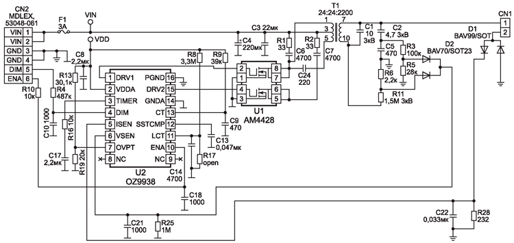
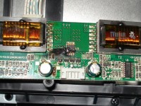
The board of such an inverter is small in size and located at the bottom of the screen. IN in this case controller U2 OZ9938 controls the keys U1 AM4428 contact CN1 goes to the lamp. Power goes through the VIN contacts, minus GND, brightness and power control goes to the DIM and ENA contacts.
INVERTER FOR LCD
In principle, there is no special difference other than a change in voltage. For example lcd inverter TVs often use 12 volts. The output can vary from 60 to 100 volts generally. This spread depends on the diagonal of the TV and, accordingly, the number of LEDs used for backlighting.
REPAIR
Anyone with a little knowledge of electronics and working with a soldering iron and a multimeter can repair the inverter with their own hands, since there is nothing extraordinary about it.
In terms of breakdowns, I can probably say that there are no major ones, everything breaks. Lamps, switches, transformers, controllers burn out.
Most often, the backlight inverter fails due to breakdowns of the electrolytic capacitors in the power supply and the power filters of the inverter itself. Losing capacity, swelling and closing the power circuit, they lower the voltage. The keys begin to work with greater overload and burn out.
IN LCD TVs More often than not, the diodes themselves burn out. When repairing a TV, you can replace the entire LED strip or check each one and replace it individually. For example, you have 3 stripes on your TV LED strips 7 diodes on each. It is known that their supply voltage is 70 volts. We divide and get 3.3 volts, look for one with a power of 1 watt to ensure normal brightness and make a replacement.
Models modern inverters are very diverse, but the principles of their construction and operation are almost the same, and this simplifies their repair.