Samsung TV matrix backlight. LED backlight driver
Many people today use LED strip to illuminate a wide variety of interior elements in their homes. Moreover, LED lighting is often located behind the TV. It’s quite easy to organize such lighting yourself if you know some of the nuances that we’ll talk about in this article.
The most in a simple way To organize this type of lighting - use a regular LED strip or PaintPack. Our article today will tell you about the benefits of backlighting a TV with an LED strip, as well as why the PaintPack system is needed.
Why is TV backlighting necessary?
It is known that watching TV in complete darkness is very harmful to the human visual system. The negative effect is especially noticeable in adults, while in children it is smoothed out due to growth and development, as well as the strong regenerative abilities of the child’s body.
Note! The harm in this situation is confirmed both by many studies and by people’s subjective feelings.
Watching TV without at least backlighting is fraught with a number of negative phenomena:
- rapid eye fatigue;
- drop in visual acuity;
- the appearance of headaches, etc.
Note! All this, especially rapid eye fatigue, is caused by the presence of too bright and noticeable contrast between the TV screen and a darkened room. In addition, the brightness of the screen itself can change dynamically, which forces the human visual system to function in extreme conditions.
A bright TV screen and a dark room are a bad combination for the eyes.
Long-term, or even worse, constant watching of TV, when there is no backlighting and the entire room is in darkness, leads to the development of stress, as well as general fatigue. Ultimately, there is a general decline in human health, a deterioration in the protective and adaptation mechanisms in his body.
Solution to the problem: external lighting
Today, the problem of watching television at night has a fairly simple solution, which can be implemented with your own hands. The solution lies in installing additional backlighting for those models that do not have the contour lighting of the screen equipped by the manufacturer.
But there are “pitfalls” here, without knowledge of which the harm to the body will continue to be caused. In this situation, the following nuances must be taken into account:
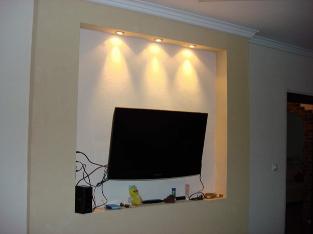
- general ceiling lighting is not suitable here, since its luminous flux will illuminate the screen. As a result, the TV's contrast will begin to decrease;
Room ceiling lighting
- A slightly better solution would be to use wall sconces, floor lamps and table lamps. But in such a situation we are faced with the problem of optimal placement of lighting fixtures, because they should not interfere with watching TV. If such lamps are located behind the viewer, they will create glare on the screen. And if they are placed near the TV, they will attract attention, distracting;
Lamp next to the TV
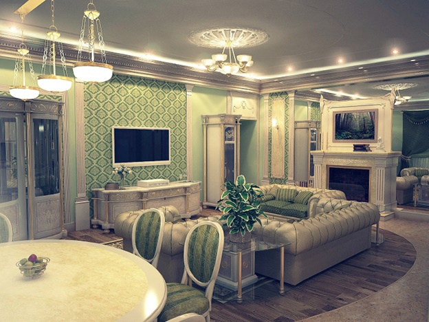
- background lighting. Creating background lighting around the TV does not have all the disadvantages of the previously listed methods of placing lighting fixtures. The advantages of this method include the fact that lighting using modern technologies(LED strips and PaintPack) can be easily organized with your own hands.
As you can see, backlighting in this situation is the best option.
Features of backlighting: what to consider
Background lighting, which you organize yourself behind the TV, must meet a number of requirements:
- be unobtrusive so as not to attract undue attention to yourself;
- give optimal level luminous flux to prevent eye fatigue from prolonged viewing of television in the dark;
Background lighting
- easy and quick to install with your own hands;
- the light sources with which it is formed should not heat up. This factor can lead to the risk of developing a fire hazard, since the TV itself, even modern models, heats up during its operation;
- lamps used for background lighting must be environmentally friendly and free of harmful substances. Such requirements are due to the fact that when placed behind equipment of this kind, they are at risk of mechanical damage. Especially if there are small children in the house who are constantly scurrying around near equipment.
Of the variety of lighting devices actively used in external and internal lighting systems, in this situation LED products, namely LED strips, most fully meet the above requirements.
Benefits of LED TV Lighting in the Background
Using an LED strip as background lighting for any equipment in the house has the following advantages:
- the ability to choose the backlight of any color. LED products have a fairly wide range of all possible colors and shades;
LED lights
- easy DIY installation. Due to the presence of a self-adhesive base, such products can be glued to any surface, even the back cover of equipment;
- excellent luminous flux, which is many times greater than all other light sources;
- no significant heating during operation;
- completely environmentally friendly products that cannot break and injure a child;
- low power consumption;
- long service period.
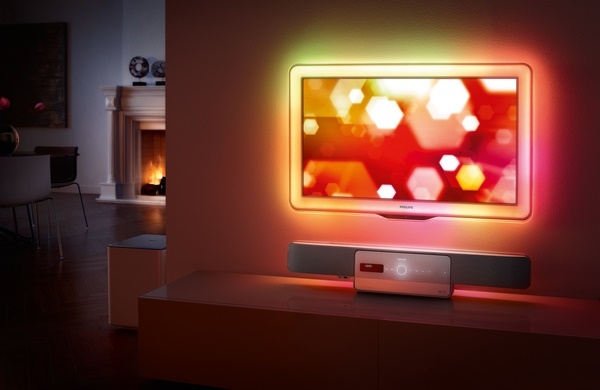
Separately, it is worth noting that as decorative and background lighting for the TV, LED Strip Light can give any room an atmosphere of celebration, romance or fabulousness.
With such advantages, it is not surprising that it is the LED strip that has become most widely used as background lighting not only for televisions, but also for various decorative elements of the interior.
Options for installing LED backlighting behind a TV
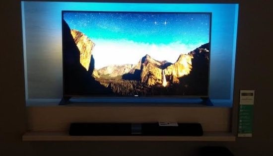
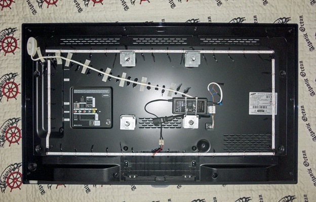
As we have already found out, the simplest and in an accessible way To make your own backlighting is to install an LED strip on the back cover of the TV. This procedure will not take you much time and will require the following steps:
- We place the TV on a previously prepared table, which is covered with a cloth. This must be done carefully so as not to damage the screen;
- along the perimeter back cover glue the LED strip. Remember that it can have any glow color;
- since the TV will heat up during its operation, the tape should additionally be placed on glue every 5-10 cm;
Installing the tape
- then solder strips of tape in the corner. You can buy special corner connectors here;
- then we connect to them a power supply with the required power for the tape used in the backlight. You will need to include a 5→12 volt relay or converter in the circuit. This is necessary if the device has USB outputs;

Connection diagram
- The backlight switch can be attached in the corner.
Note! The tape must be held firmly so as not to cause a short circuit.
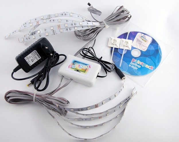
PaintPack system
In addition, you can use PaintPack lighting systems.
The PaintPack system is a small package. Removable LED strips are connected to it on both sides. PaintPack is also equipped with an indicator, power connector and microUSB, through which it can be connected to a computer. PaintPack also includes a master connector. It allows you to connect two devices in series.
Note! This fixture is great for background lighting and computer monitors.
The system housing should be installed on the back of the TV. Next, using the algorithm described above, we mount and connect the LED strips.
If you plan to connect PaintPack via a USB connector to a computer, you will need to install the required drivers, as well as configure the device in the bundled program. For this you will need the AmbiBox package.
Conclusion
When deciding to create a TV backlight, you won’t find a better light source than an LED strip. In this situation, all manipulations are quite easy to do with your own hands, which is another plus. Moreover, using PaintPack, you will achieve more manufacturability of the background lighting created by yourself.
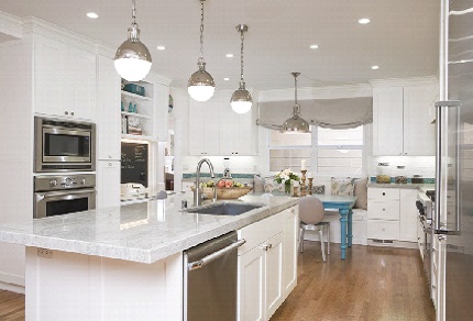 Lighting in the kitchen of a small apartment
TV LG 32LN540V
A TV came in for repair with the following fault:
"No image"
When you turn on the TV, the control panel is on, but there is no image.
The sound cannot be determined due to the difference in channel settings, due to the difference in terrain (distance from the tower)
The parts were opened and inspected.
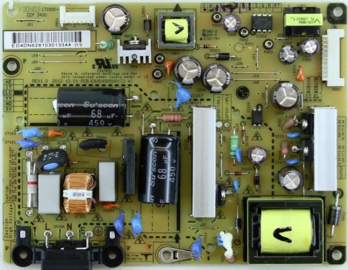
First, an external inspection of the TV's power supply was carried out:
The power supply is common among TV models LG 32LN540, 32LN 541, 32LN 548.
PSU: EAX64905001 revision 2.8
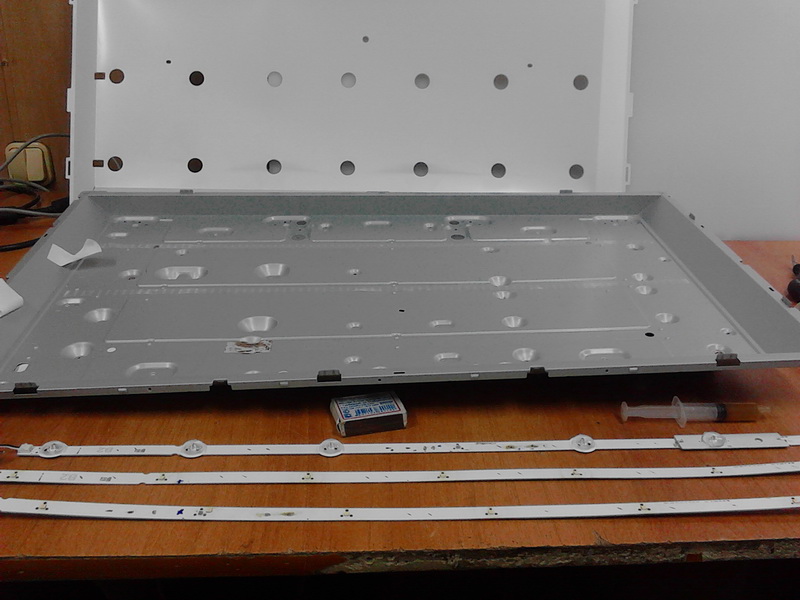
The TV matrix was disassembled and the following was found:
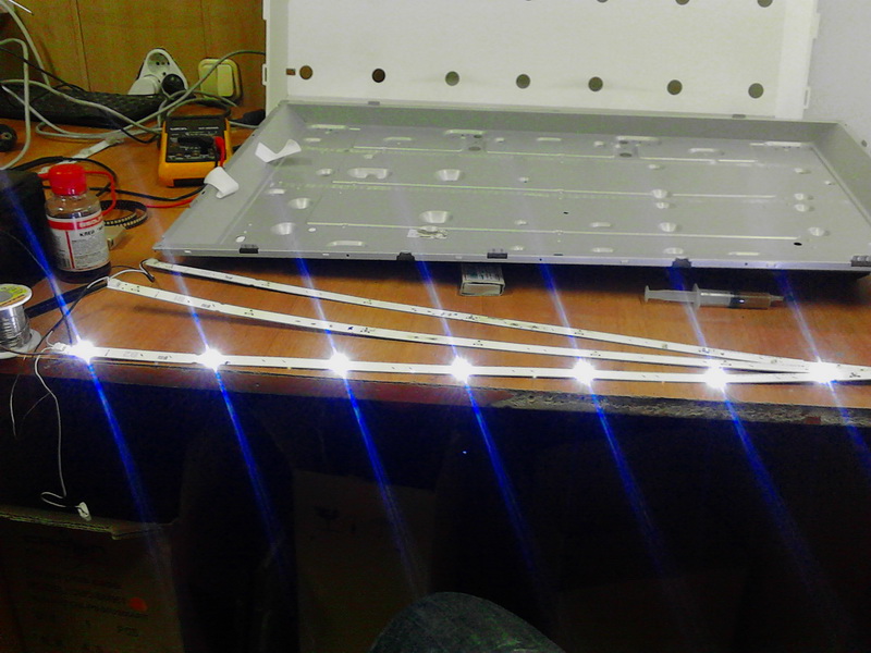
The backlight consists of 3 strips of 7 LEDs each, LEDs 1W 3v. The continuity check of the tapes showed a malfunction of the 1st LED in each tape.
Repair:faulty LEDs were replaced. After testing, the TV was given to the client..
BUT,
A month later the TV was returned by the client with the same problem: “no picture”
however, other LEDs have now burned out.
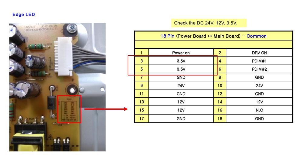
PSU testing showed:
- The ST-BY 3.5 v voltage is present, and the standby LED indicator lights up
- There is no voltage of 12 and 24 V of the 18-pin MainBoard - PowerBoard connector. There is no backlight supply voltage after switching on.
Obviously the power supply goes into protection for some reason, or there is a fault in the power supply along the 12 and 24 V lines
Based on the analysis of repairs of these models, as well as due to the return after a previous repair, all LEDs in the strips were replaced.
Moreover:
It is no longer a secret that in LED TVs LG of similar models, the backlight is made using low quality LEDs. Thismodels 32LN540x -548 -541. In this case, the LED driver is working, opening the matrix shows a break (malfunction) of one or more LEDs LED backlight.
As the practice of backlight repair shows, in addition to replacing the backlight LEDs, it is necessary to modify the power supply in order to reduce the current supplying the monitor's LED strip. In these models, the current is too high, plus low-quality LEDs. As a result, the repair consists of:
1. When replacing all LEDs or backlight strips entirely, I replaced all 21 LEDs with similar ones with the following characteristics:
forward current: 400mA
Pulse Forward Current: 650mA
Reverse Current: 25mA
Reverse Voltage(VR): 0.8-1.2V(mA)
Power Dissipation (PD): 1460 MW
Forward voltage: 3.05-3.65 V

2. After replacement, mandatory modification of the power supply is required, namely the power supply circuit for LED strips (driver circuit), in in this case MP3202 drivers.
On LG TVs that use LED drivers with the MAP3202 PWM controller,
The popular PSU EAX64905001, a current sensor consists of a set of pairs of low-resistance resistors.
Having unsoldered one of the pairs, we increase the sensor rating, which increases the depth of PWM OOS and
proportionally reduces the current in the LEDs.
In this model, by removing one circuit from the current sensor circuit, I achieved a reduction in the current on the backlight strips.
According to the parallel R formula:
With Rd=2.08 Om increased the resistance to Rd = 2.7 Om, which generally led to a decrease in the LED backlight current, plus the replacement of all LEDs, because they had already been subjected to work in extreme conditions with high current.....
Something like this.........
Read more about the modification of the power supply for LG TVs of the same series here:
Driver LED backlight
(replacing CCFL lamps with LEDs)

LED DRIVER, which we will talk about today, is a module with a minimum set of electronic components placed on a small printed circuit board the size 65mm x 20mm. Main destination - For LCD backlight monitor panels , in general, you can apply it anywhere, it all depends on your imagination. The compact dimensions of the module allow you to freely position it inside the monitor and secure it in a convenient place; for this purpose, there is a small hole located on the side of the board, or it can be easily attached using double-sided tape. The LED driver kit we purchased includes two LED strips of length 533mm - 96 LEDs on each and one wire cable for connecting power and controlling the module. Please note that the package may not include led strips, and also the length of the rulers may be greater (or less) than indicated by us; check the availability and length of the rulers with the seller. Undoubtedly, since we are talking about the main purpose, the length of the rulers purchased will depend on the diagonal of the monitor. AND little advice: it is better to select the length not end-to-end, but with a small margin. On the board itself, except for the designation CA-155 REV:01, there are no longer any markings of belonging to one or another model of such devices. Manufacturer - China.
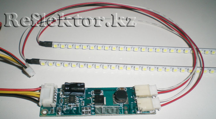 Module CA-155 REV:01
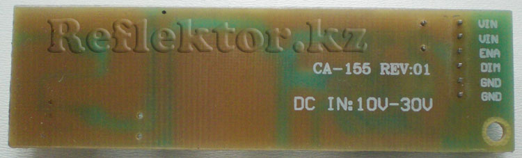
Let's see what's on the board. The module board has two connectors that supply power for the LEDs and a backlight driver chip DF6113 (8-pin SOP-8L), N-channel MOSFET transistor, one electrolytic capacitor, inductor, seven resistors, four ceramic capacitors and one Schottky diode SS210. All elements installed on the board are in SMD cases, with the exception of the electrolytic capacitor. The connector for connecting power and driver control has six pins: VIN- supply voltage 10v - 24v (2 contacts), ENA(Enable) - enable/disable the driver, DIM(Dimming voltage) - brightness adjustment, GND(2 contacts). We want to say right away that the maximum voltage of 30 volts indicated with reverse side boards - extremely undesirable, high voltage “ceiling” for DF6113 according to the datasheet 24 volts! We will consider this not an intentionally indicated figure, but simply a typo. Those interested can go through for more detailed information.
Let's list some characteristics of the microcircuit specified in the documentation: input voltage in the range from 5 to 24 volts, soft start, brightness adjustment from 10% to 100%, short circuit and overvoltage protection, control of the LED line current. The chip supports three brightness control modes - separate, single signal, and mixed control. This module implements inverted analog brightness control, in which the maximum brightness of the LEDs is achieved at zero voltage at the DIM connector pin. A decrease in brightness of up to 10% occurs when the voltage level at the same pin (DIM) is increased to three volts. What does it mean? To make it clearer, let's explain in simple language- this means that the slider on the monitor screen, which shows the brightness adjustment, will work in the opposite direction, i.e., when the brightness adjustment is at 100%, the screen will be darkened and vice versa. We are not at all happy with this option, so we immediately make improvements. After making small and simple changes to the circuit, we get direct control brightness, and also increase the adjustment range. For modification, we used one 1N4148 diode, leaving the values of the current-setting resistors R4 and R7 unchanged. We connect the driver to the monitor and check the result of the changes - now the brightness increases towards 100%, and at the same time the brightness range has noticeably increased. By adding a few more elements, you can further improve the control of the LEDs, resulting in greater linearity and wider control range. The microcircuit works quite well with PWM brightness control. Below is a schematic picture of the driver that we reproduced from this module, with an exact indication of the resistance values, as well as the modification option we settled on.
 Diagram of LED backlight module CA-155 REV:01
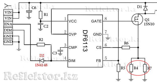 Revision option
Briefly about the LED line. As we said above, the length of the rulers is selected taking into account the diagonal of the monitor; our ruler, which has a length of 533mm, turns out to be too long, with a margin, and since we installed the backlight in 17 BenQ inch monitor , then shortened it to 66 LEDs (360mm) . The ruler is easily cut to the desired size; to understand how to cut it correctly, just look at the image below, which schematically shows the tracks and the location of the LEDs on the ruler. All LEDs form a parallel-series connection circuit; groups consisting of three series-connected LEDs are connected in parallel to the plus and minus buses. On the back of the ruler there is a marking - , from which the length, number and type of LEDs installed on it become clear. The width of the ruler is 3.8mm, distance between LEDs - 2mm. The type of LED is quite popular - SMD3528, with dimensions 3.5 X 2.8 x 1.8 mm (L x W x H), all parameters of the LED can be found by opening the documentation.
 Cutting line when shortening the LED line
LED strip JH-LED96-533MM-3528-12A

Well, before installing the LEDs in the monitor, let’s once again measure the voltage and current on the driver board and the LED strips shortened to our diagonal. Supply voltage to the module coming from the monitor = 14.8v, LED voltage = 9.2v, LED line current at maximum brightness = 460mA. At the same time, the LED line does not “boil” and does not get very hot; it is warm to the touch. You can remove old lamps CCFL and install LED strips. Perhaps in the next article we will show the entire replacement process, with photographs, and tell you how to prevent the bright glow of the LEDs from being noticeable through the matrix, in the places where they are attached.

All article materials belong to the site. When using these materials, an active link to the site is required!