Automatic lighting sensor. Let's consider all types of remote light switches for home and garden
The infrastructure of any settlement requires the presence of powerful lighting devices. Thanks to the time relay, they are able to turn off and start working at the right time.
Automated operation of lamps is also used on personal plot. This consumes significantly less power and adds a motion sensor to the relay.
Control cabinet
The control cabinet is the center in which all the circuits are collected, from where the load is distributed and full control over the lighting is carried out. Protection of photo relays of lamps from short circuits and voltage surges is also carried out through this control panel.

Operating diagram of the street lighting control cabinet: 1 - electric meter, 2 - lock, 3 - protection, 4 - cabinet. All information and indicators are transmitted via the Internet
Also, based on the service life, equipment is being updated here - the longer any cable or circuit operates, the greater the chance that the control cabinet will have to be de-energized and worn-out elements replaced for the safety of the site.

Option for assembling a street lighting control cabinet
The cabinet performs the main task: it controls the operation of the desired relay depending on the time of day, provides guidance using the remote control, and regulates the brightness of the lamps after the photo relay is activated.
What to connect?
These can be ordinary street lamps with simple relay, controlled from a remote control through a control box, tiny LED bulbs along the paths, suspended illumination and a lamp above front door. That is, any lighting fixture located outside the home, but falling within the coverage radius of the remote control.
Types of control
The following systems are considered traditional:
- magnetic or induction ballast - lights the lamp with an inrush of current, but power surges often occur, which is why you have to install an additional relay;
- electronic ballast – does not use a starter, there is no noise, no flickering, reduced energy consumption. It distorts the radio transmission, quickly disables the photo relay, the result is that it does not work depending on the time of day;
- option for enterprises - based on the calendar and daily time, controls lighting, starting from the “working/holiday/weekend” scheme.

The simplest and cheapest scheme for controlling street lighting using a photo relay, based on this moment the cost of the photo relay is 300-400 rubles; all street lighting in the area can be connected to it
Street lighting control uses three types of devices:

Control over area lighting
If finances allow you to stretch a separate cable to each lamp with a relay on the site, then one control cabinet will be installed inside the house, and another one at the gate. But such a shield must operate in parallel with the second one, which means that each unit will consume the energy of a full-fledged cable channel.

Garden lights for lighting the area, are not afraid of water (IP66), have built-in motion sensors and a control panel
The following system would be optimal: the first cabinet is installed at the gate, and lights with motion sensors and photo relays located along the path are connected to its controller. The second cabinet is placed directly inside the room - remote control will be carried out from here. The scheme is simple: certain lamps are connected to the channel that goes to the control unit, and a signal is sent from the remote control.
A popular unit is one that controls the automatic lighting system and has a large number of additional capabilities. Among them are a circuit for providing illumination, remote control of a photo relay. The shield can also issue a command to automatically de-energize the perimeter of the house. And the most common and budget cabinet assumes the presence of 6 working channels, of which no more than 4 are usually used.
Remote control
When all the cables are connected to the future automatic lighting system and pulled into the control cabinet, the process of improving it begins. A controller is installed on each lamp, thanks to which it is possible to receive commands via a radio channel. Signals are transmitted using the remote control. Externally, such a controller looks like a miniature switchboard, the power supply of which is represented by batteries.
Another option for transmitting a command over a radio channel is possible using a sensor capable of recognizing radio waves. The device is also controlled using a remote control.
Very good in terms of budget and practical use of flashlights on solar powered. Their installation does not require meters of cable and a control panel. Using radio waves of different frequencies, individual illuminated areas can be identified. The main advantage of using radio channels is complete coverage of the area (especially with the use of an amplifier).

Lighting control using a smartphone
Remote control of site lighting almost always uses a distribution cabinet. The controller can transmit signals in the following ways:
- the shield sends RF signals through the cable - these signals are used to automatically control individual lighting fixtures. The controller may not be able to cope with its task due to damage on the line. The full effect can only be achieved with a separate connection of each relay;
- gsm signals. The control is tied to the smartphone program, the command is sent to the control panel. The main drawback that the system cannot avoid is overload of the gsm network, or the owner being outside the coverage area. But at the same time, using this method does not waste the budget, since the gsm network is publicly available;
- radio channels are good for monitoring a large area. The device may not respond to the signal due to possible interference, so it is better to purchase an amplifier;
- an automated system based on digital control requires a large investment of time and effort. The returns are low due to regular crashes. A separate control unit is desirable for each lamp; the device requires adjustment every few days.
Regardless of the chosen method, be it a gsm network or a cable, automatic control is based on the rules of the following scheme:
- control panel over a separate relay or group of lights;
- control cabinet over a larger area (block, street, apartment yard);
- the main shield in charge of the area.
Light sensor LXP-02 and LXP-03. Installation
In this article we will consider the issues of installing and connecting a light sensor. Also given electrical circuits the most popular models of light sensors.
Let me remind you that this device is widely used in the field of home automation to turn on/off electric lighting depending on the light level outside. The names may be different - light sensor, light sensor, light control switch or photo relay, but the essence is the same.
I spoke in detail about such a sensor in the first part of the article -. Its structure, operation and characteristics are discussed in detail there.
So I’ll get straight to the point:
Connecting the light sensor
I will give three options for the connection diagram, they are all identical, the only difference is in the display method.
1. Circuit similar to a motion sensor
The connection diagram for the light sensor is completely identical to. Only the “filling” of the sensors differs.

The diagram is taken from the article about the motion sensor, link above.
2. Diagram from the instructions for the light sensor
This is how the light sensor connection diagram is shown in the instructions:

Light sensor LXP. Connection diagram from the instructions
3. Connection based on photo sensor
For those who like everything to be “at their fingertips”, here is the following picture:

A short explanation of the connection diagrams:
- The brown wire receives phase.
- Zero is connected to the blue wire.
- A load is connected to the red wire (the first terminal of the lamp).
- The second terminal of the lamp is connected to zero (in the same place as the blue wire of the sensor)
It is worth adding that light sensors can be connected in the same way as conventional switches - in series and in parallel, if necessary. An example can be seen in the article about.
So, we figured out the connection, now
Light sensor installation
It would seem, what is wise here? I screwed it on (see the picture at the beginning of the article), connected it, configured it, and that’s it! But sometimes the installation location is chosen poorly, and problems begin.
On our street at one time the street lights turned on in an intricate way in the evening. They will turn on, go out, turn on again, and so on with a period of about 1 minute. Then, with the onset of good darkness, they turned on completely.
Why is that? The light sensor was simply mistakenly installed in the illumination zone of the flashlight being turned on. It turns out: it became dark - the sensor worked - the flashlight came on - it became light - the sensor turned off - it became dark... And so on, a vicious circle.
Setup and calibration
When setting up the light sensor, it is important to use the black bag that comes with the sensor. This bag serves to simulate night.

Bag for setting up the light sensor
Among the adjustment controls in the light sensor, there is only a light level control (LUX). It sets the level at which the sensor's internal relay is triggered.
The level setting is described in more detail in the description of the circuit diagram below.
There are the simplest light sensors (for example, LXP-01), which have no adjustments at all. There are advanced ones that also have an on/off delay time regulator.
Well, now the most interesting thing -
Light sensor circuits
Undoubtedly, to quickly and easily repair a light sensor, you need its diagram, from which it will immediately become clear what is connected where and how it works. Below are a couple of sensor diagrams and repair recommendations. If you have questions about repairs, ask in the comments.
The circuit is copied exactly from the board shown in the link at the beginning of the article. It is worth noting that the manufacturer is constantly working to improve its device (price/quality), so the scheme may change.

But the principle remains the same:
The supply voltage of 220 Volts is supplied through terminals L (phase) and N (zero).
Phase and zero can be “confused”, just as in principle it is possible (but not recommended) to turn off zero and not phase in conventional switches. Only safety and common sense suffer.
Maybe this will be interesting:
The voltage is rectified by a diode bridge (4 diodes of type 1N4007), filtered (smoothed) by an electrolytic capacitor, and stabilized at a level of +22...24 Volts by a zener diode of type 1N4748.
Further constant pressure powers the rest of the circuit, which works like this. At the output of the resistive divider 68k - VR - Photoresistor, a voltage is formed that is inversely proportional to the illumination. The VR trimmer with a resistance of 1 MOhm is the same “twist” with which the desired response level is set.
It is not a fact that a photoresistor is installed in such circuits; a photodiode may also be installed, but the principle is the same.
If you want to save energy, set the maximum resistance, turn it clockwise ( LUX-), and it will work when it is already completely dark.
If you want the street lighting to turn on at the slightest cloud, turn the regulator in the other direction ( LUX+).
When darkness sets in, the illumination drops, the resistance of the photoresistor increases, and the voltage at the base of the transistor increases. And it reaches such a level that the transistor opens, and a current sufficient to turn on the relay flows through the collector CA. The relay with its contacts turns on the load, which is connected through the output LOAD.
At the same time, the LED lights up, and a 47 uF capacitor in the base circuit smoothes out all processes so that the relay does not click too quickly, for example, if it is blocked by a tree branch swaying in the wind.
Knowing the principle of operation of the circuit, it is easy to repair it. And if you want to understand the repair in more detail, then the article describes step by step the methodology and philosophy for repairing such devices.
A selection of amateur radio designs various types automatic switches and lighting control circuits for lighting both indoors and outdoors.
When lighting long corridors, staircases, entrances, hangars and similar places where it is necessary to turn on or off light from two or more places, corridor switches are usually used. Install them in opposite parts of the corridor. The circuit is standard and is probably known to any electrician, but to change the state of such a switch, the switch must be flipped to the opposite position to the previous position. That's why typical diagram requires laying three wires to the switches instead of two, and this is only under the condition that the lighting needs to be controlled from two places. In this article, we will show clear examples of how to circumvent such shortcomings.
Such schemes are ideal for use in places where human presence is not prolonged. The light stays on just as long as you need it. After leaving the place, the lighting turns off with a short time delay, which allows you to save a lot of electricity. In addition, such amateur radio designs are an excellent way to scare away petty thieves who are scared by the light suddenly turning on.

The most common design is circuit breaker light control based on a motion sensor and AVR microcontroller, but if a person just stands, the lighting will turn off. The circuit based on a pyrodetector is quite complex and requires adjustment and adjustment. But the circuit based on an ultrasonic sensor is free of these disadvantages.

An automatic light switch is capable of turning on or off a light or other load at a programmed time each day. It is assembled using a PIC12C508 microcontroller. (Firmware for MK is included).
When you find yourself in the dark, it is not always possible to immediately find the light switch, especially if it is located far from the door. A similar situation may occur in the case of leaving the room, when we turn off the lighting and then are forced to feel our way to the exit. An acoustic switch, the circuit and design of which are discussed in this article, can save you from problems.

The clap switch device is triggered by a clap sound signal. If the volume is sufficient, then the circuit turns on the lighting in the entrance (or other room) for one minute. The first design has one interesting feature to prevent cycling of work, namely, the microphone turns off automatically after turning on the lights, and turns back on only a couple of seconds after the lights turn off.
The circuit breaker is based on the domestic microcircuit KR512PS10, which is a multifunctional multivibrator - counter. The microcircuit contains logic inverters for an RC circuit or a quartz multivibrator and a counter with a maximum division factor of 235929600. That is, when using a standard clock resonator at 32768 Hz and selecting the maximum division factor mode, the output of the counter will be pulses with a period of 120 minutes. And the output unit appears after 60 minutes. Thus, if we set the moment when a unit appears at the output after zeroing, we obtain a time interval equal to one hour. The outputs of the microcircuit 10 and 9 are made with open drains, so pull-up resistors are needed there. Well, now I’ll tell you a little about the other pins of the microcircuit and their purpose (it may be useful when upgrading or modifying the circuit for another purpose). And so, pin 3 is the STOP pin; when a logical one is applied to it, the counter freezes. Pin 2 - zeroing, apply one to it and the counter is reset. Pin 11 controls the level at output 10. If pin 11 is zero, then the level at pin 10 will be the opposite of the level at pin 9.

Automatic switch circuit for KR512PS10
If there is one, then pins 10 and 9 work the same way. To set the division coefficient, use pins 1, 12, 15, 13, 14. If they are all zeros, then the division coefficient will be the minimum base one, equal to 1024. When one is applied to any of these setting pins, the base coefficient is multiplied by the coefficient of this pin. For example, if you apply one to pin 1 (128), then the division coefficient will be equal to 128x1024=131072. A unit can be applied to only one of pins 13, 14 or 15, while the other two of this three pins must have zeros. But units can be supplied to pins 1 and 12 simultaneously. All division coefficients whose outputs are supplied with units are multiplied, and then the resulting result is multiplied by the base coefficient of 1024. Turning on the night light can be done in two ways. Initially, the night light is turned on as usual - with the power switch S2. In this case, the lamp immediately lights up and the time countdown begins. If it was previously turned on and turned off, then you can turn it on again either by pressing the S1 button or by turning it off and then on with the S2 switch. After any of the above switching options, counter D1 is reset to zero (by capacitor C1 or button S1). In this state, the counter outputs (pins 9 and 10) are zeros. Transistor VT1 is closed and does not bypass the gate circuit field effect transistor VT2. Gate VT2 receives an opening voltage through resistor R6, which is limited to an acceptable level by zener diode VD2.
Therefore, transistor VT2 opens and turns on lamp H1 (which is powered by a pulsating voltage through the rectifier bridge VD3-VD6. This unusual control circuit for a high-voltage field-effect transistor is due to the fact that the nameplate supply voltage of the KR512PS10 is 5V, and the voltage at the gate of the field-effect transistor IRF840, which ensures it full opening, according to the reference data, must be at least 8V, therefore, the VT2 gate and the microcircuit are powered from different sources, and the VT1 transistor functions not only as an inverter, but also as a level matcher. An hour after zeroing, logical signals appear on pins 9 and 10 of D1. pin 9 stops the counter by sending a logical one to pin 11. And pin 10 opens the transistor VT1. When it opens, it bypasses the gate circuit of the field-effect transistor VT2 and the voltage at its gate drops to zero and the lamp H1 goes out. 5V (or rather, 4.7V) from the parametric stabilizer on the zener diode VD1 and resistor R5. Button S1 should not be locked. You can do without this button altogether.
In this case, to turn on the night light after it automatic shutdown you will need to turn it off using the power switch S2 and turn it on again. By the way, you can also abandon the power switch in favor of the S1 button. But then you can turn off the night light ahead of time only by unplugging the plug from the power outlet. And there is also a third option - installing a switch instead of a button. Then the switch, being on, will block the timer, and the light will not turn off automatically. And to switch to automatic mode, you will need to turn off the switch installed instead of S1. Quartz crystal Q1 is a standard clock crystal. It can be replaced with an imported clock resonator at 16384 Hz (from Chinese quartz alarm clocks), but then the time the night light is on will accordingly double.
In the absence of the necessary quartz resonator, and also, if you want to make a continuously adjustable time interval, you can make the multivibrator part of the circuit using RC elements with a variable resistor, as shown in the second figure. The IRF840 transistor can be replaced with a domestic analogue such as KP707B, KP707V. Transistor KT3102 - almost any ordinary low-power transistor structures p-p-p, for example, KT315. The KS147A zener diode can be replaced with any 4.7 - 5.1V zener diode. There is a large selection of imported zener diodes for this voltage. The same can be said about the D814D-1 zener diode, but it should only be at a low voltage in the range from 9 to 13V. The rectifier bridge is made on 1N4007 diodes, these are now perhaps the most common rectifiers medium power operating on mains voltage. Of course, you can replace with any others rectifier diodes with direct current parameters and reverse voltage no less than this. Capacitor C4 must be for a voltage of at least 6V, and capacitor C5 for a voltage of at least 12V. Nightlights are usually equipped with low-power lamps. If this is an incandescent lamp, then its power does not exceed 25-40 W. However, this circuit allows working with lamps with a power of up to 200 W inclusive (without a radiator for VT2). Although, this may only matter if this circuit is not used to control a night light.
The circuits discussed in this article are designed to automatically turn on street lighting at nightfall and automatically turn off at dawn. Some of them have original circuit solutions.
The proposed amateur radio design smoothly turns on and off the staircase lighting when a person appears in the area of action of the pyroelectric motion sensor (MS), and thanks to the K145AP2 microassembly, the brightness smoothly increases when the light is turned on and decreases when turned off.
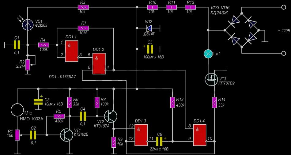
The automatic switch consists of a light sensor, a converted Chinese quartz alarm clock and a trigger combining them with a high-voltage switch at the output. Phototransistor FT1 is used as a light sensor. By selecting the resistance of resistor R1, its sensitivity is adjusted so that during the day the voltage on R1 is above the threshold for switching the logic element to one, and at night below this threshold. If the sensor is configured correctly, then the voltage at pin 1 of D1.1 is still quite light - a logical unit. As it darkens, the phototransistor closes and the voltage at pin 1 of D1.1 decreases. At some point it reaches the upper threshold of logical zero. This causes the launch of the one-shot D1.1-D1.2, which generates a pulse that sets the trigger D1.3-D1.4 to one.

Automatic switch circuit from an alarm clock
The voltage from the output of element D1.3 is supplied to the gate of the high-voltage field-effect transistor VT1. Its channel opens and turns on the lamp lamp. Gate VT1 is connected to output D1.3 through resistor R4, which reduces the load on the output of the logic element from charging the relatively large gate capacitance of the transistor. The presence of the R4-VD2 circuit significantly facilitates the operation of the logic chip and eliminates the tendency to fail. The lamp is on. The trigger is in a steady state, so it remains on even if light from the lamp hits the phototransistor. A Chinese quartz alarm clock mechanism is used to turn off the lamp. The alarm clock must be set to real time, and the call is for the time when the lamp should be turned off, for example, for two hours. The alarm clock is being redesigned. The diagram highlights the alarm clock circuit; it shows the alarm clock electronic device board with all connections. The board is shown as it looks. B is the alarm beeper, L is its stepper electric drive, S is the switch connected to the clock mechanism. The battery is also indicated. To give a command to turn off the lamp, a mechanical switch S is used, connected to the alarm mechanism. To disconnect it from the alarm clock chip you need to cut printed track on the board. And then solder the wire to the printed pad connected to switch S. All these operations can be done without removing the board from the alarm clock. Remove carefully back cover clock mechanism, after removing all the handles.
You need to act carefully so that the mechanism does not fall apart. Then, using a thin awl, we tear the printed track on the board and solder the mounting wire with a thin soldering iron. After this, we bring the wire into the battery compartment and very carefully close the lid so that all the gears fit into their holes. As soon as the alarm clock hands are set to the specified time, for example, at 2-00, the S contacts close and close pin 13 D1.4 to a common negative.
This is equivalent to applying a logical zero to this output. The trigger switches to the zero state, the voltage at output D1.3 drops, and VT1 closes, turning off lamp H1. The alarm clock has a standard 12-hour scale, so the contacts will close twice a day, but this is not significant, since, for example, closing them at 2-00 in the afternoon will not lead to anything, because during the day the lights are already off. Although, an incorrect setting option is also possible, for example, at 7-00, that is, if you want the light to be on all night and turn off at dawn, at 7-00 in the morning. But, if it gets dark for you at 18-00 (6-00 pm), then the lights will turn off at 19-00 (7-00 am). Therefore, such a setting should be avoided - it is necessary that the alarm clock setting corresponds to daytime and nighttime, and not morning and evening. The circuit and the lamp are powered by a constant pulsating current through a rectifier using diodes VD3-VD6. Voltage is supplied to the microcircuit from a parametric stabilizer using resistors R5-R7 and zener diode VD1.
Switch S2 is used to manually turn on the lamp. As a photosensor, you can use a phototransistor, a photoresistor, a photodiode connected by a photoresistor (reverse polarity). I do not know the brand of phototransistor used. I took a phototransistor from disassembling the tape mechanism of an old faulty VCR. I experimentally checked where each pin was and that the resistance R1 needed was about 70 kOhm (I set it to 68 kOhm). When using another phototransistor, photoresistor or photodiode, you will need to carry out the same experiments to select the required resistance R1. You can first replace R1 with two variable resistors of 1 megaohm and 10 kohm, connecting them in series.
By experimenting with light, you will find the required resistance, then measure it and replace it with a fixed resistor that is close in value. Without a radiator and with the diodes shown in the diagram, the KP707V2 transistor can switch a lamp with a power of up to 150 W inclusive. KD243Zh diodes can be replaced with KD243G-E, 1 N4004-1 N4007 or other similar ones. The K561LA7 chip can be replaced with a K176LA7 or CD4011. Zener diode VD2 - any voltage 12V, for example, KS512. The KP707V2 transistor can be replaced with KP707A1, KP707B2 or IRF840. Quartz alarm clock - “KANSAI QUARZ”, at least that’s what it says on its dial.
Many people, when leaving the room, forget to turn off the light in the toilet, bathroom or hallway. And if they don’t forget, the switch in these places can quickly break due to frequent mechanical stress. All this indirectly suggests the need to install an automatic lighting control unit, for example, such amateur radio developments as are described in this article. The proposed block diagrams automatically control the lighting, and the control element in them is the door in the reed sensor system.
The circuit breaker is assembled using only two digital chips DD1 and DD2, one transistor; and one SCR. It contains a pulse generator built on logic elements DD1.2-DD1.4, capacitor C7 and resistor R10, and produces rectangular pulses with a frequency of 10,000 Hz (or 10 kHz - this is audio frequency). Moreover, frequency stability is not particularly important. Therefore, the repetition period of these pulses is 0.1 ms (100 μs). These pulses are almost symmetrical, so the duration of each pulse (or pause between them) is approximately 50 μs.
On logic elements DD1.1, DD2.1, capacitors C1-C3, resistors R1, R2, diode VD1 and antenna WA1 with connector X1, a capacitive relay is made that responds to the capacitance between the antenna and the network wires. When this capacitance is insignificant (less than 15 pF), rectangular pulses of the same frequency of 10 kHz are formed at the output of element DD1.1, but the pause between them is reduced (due to the differentiating chain C1R1) to 0.01 ms (10 μs). It is clear that the pulse duration is 100 - 10 = 90 µs. However, in such a short time, capacitor C3 still manages to be almost completely discharged (through diode VD1), since its charging time (through resistor R2) is long and approximately equal to 70 ms (70,000 μs).

Automatic switch lamp diagram
Since the capacitor is charged only at the time when there is high level voltage (be it a pulse or just a constant level), during a pulse lasting 90 μs, capacitor C3 does not have time to charge any noticeably, but; therefore, the output of element DD2.1 always remains at a high voltage level. When the capacitance between the WA1 antenna and the network wires increases (for example, due to the human body) to 15 pF or more, the amplitude pulse signal at the inputs of element DD1.1 will decrease so much that the pulses at the output of this element will disappear and turn into a constant high level. Now capacitor C3 can be charged through resistor R2, and the output of element DD2.1 is set to a low level.
It is he who triggers the one-shot (waiting multivibrator), assembled on logic elements DD2.2, DD2.3, capacitor C4 and resistors R3, R4. While the capacitance of the antenna circuit is small, which is why there is a high voltage level at the output of element DD2.1, the monostable is in a state in which the output of element DD2.2 will be low, and the output of DD2.3 will be high. The timing capacitor C4 is discharged (through resistor R3 and the input circuit of element DD2.3). However, as soon as the capacitance increases noticeably and a low level appears at the output of element DD2.1, the monostable will immediately generate a time delay, at the specified ratings of the C4R3R4 circuit, equal to approximately 20 s.
Just at this time, a low level will appear at the output of element DD2.3, and a high level at the output of DD2.2. The latter is capable of opening an electronic key made on a logical element DD2.4, transistor VT1, diode VD3 and resistors R5-R8. But this key does not remain open all the time, which would be clearly impractical both in terms of energy consumption and, most importantly, due to the completely useless heating of the control junction of the VS1 thyristor. Therefore, the electronic switch is activated only at the beginning of each half-cycle of the network, when the voltage across resistor R5 increases once again to approximately 5 V.
At this point in time, at the output of element DD2.4, instead of a high voltage level, a low voltage level appears, due to which first the transistor VT1 and then the trinistor VS1 open. But as soon as the latter opens, the voltage on it will drop significantly, which will cause the voltage at the upper (according to the circuit) input of the element DD2.4 to decrease, and therefore the low level at the output of this element will again abruptly be replaced by a high one, which will cause the automatic closing of transistor VT1 . But the thyristor VS1 will remain open (on) during this half-cycle.
During the next half-cycle everything will repeat in the same sequence. Thus, the electronic key opens only for a few microseconds required to turn on the SCR VS1, and then closes again once again. Thanks to this, not only the power consumption and heating of the SCR are reduced, but also the level of emitted radio interference is sharply reduced. When the 20-second exposure ends, and the person has already left the “magic” mat, a high level appears again at the output of the DD2.3 element, and a low level at the output of DD2.2. The latter locks the electronic key at the lower input of element DD2.4. In this case, transistor VT1, and therefore thyristor VS1, can no longer be opened (at the top input of element DD2.4 in the diagram) by synchronizing network pulses. If the shutter speed has expired, but the person still remains on the mat (on the WA1 antenna), the electronic key will not lock until the person leaves the mat.
As can be seen from Fig. 1, the SCR VS1 is capable of closing the horizontal (according to the circuit) diagonal of the diode bridge VD5. But this is equivalent to closing the vertical diagonal of the same bridge. Therefore, when the thyristor VS1 is open, the lamp EL1 is on; when it is not open, the lamp is extinguished. Lamp EL1 and switch SA1 are standard electrical appliances available in the hallway. So, with switch SA1 you can still turn on lamp EL1 at any time, regardless of the machine. It can be turned off only when the thyristor VS1 is closed. However, it is also important that after closing the contacts of switch SA1, the machine will be de-energized. Therefore, the formation of the time delay can always be interrupted at will by closing and then opening switch SA1. The machine is powered by a parametric stabilizer containing ballast resistor R9, rectifier diode VD4 and zener diode VD2. This stabilizer produces a constant voltage of about 10 V, which is filtered by capacitors C6 and C5, with capacitor C6 smoothing out low-frequency ripples of this voltage, and C5 smoothing out high-frequency ripples.
Let's briefly consider the operation of the machine (assuming that switch SA1 is open). As long as the WA1 antenna is not blocked by the capacitance of the human body, there is a constant high level at the output of the DD2.1 element. Therefore, the one-shot device is in standby mode, in which there is a low level at the output of element DD2.2, which locks (at the lower input of element DD2.4) the electronic key. As a result, the thyristor VS1 is not opened by clock pulses arriving at the upper input of element DD2.4 from bridge VD5 through resistor R6. When a person blocks the antenna circuit, a low level appears at the output of the DD2.1 element, triggering the monostable, and a high level appears at the output of the DD2.2 element, opening the electronic key and the thyristor VS1 for 20 s (the EL1 lamp is lit during this time). If by that time the blocking of the antenna circuit has stopped (the person has left the mat), the EL1 lamp goes out, but if not, it continues to light until the person leaves the mat.
In any case, the one-shot (and the machine as a whole) again goes into standby mode. To turn off the light ahead of schedule (without waiting 20 seconds), if you suddenly need it, just close and open switch SA1. Then the machine also goes into standby mode. The required sensitivity of the machine depends on the size of the WA1 antenna, the thickness of the mat and other factors that are difficult to take into account. Therefore, the desired sensitivity is selected by changing the resistance of resistor R1. Thus, an increase in its resistance leads to an increase in sensitivity, and vice versa. However, one should not get carried away with excessive sensitivity for two reasons. Firstly, increasing the resistance of resistor R1 above 1 MOhm, as a rule, requires filling it with varnish in order to eliminate the influence of air humidity on the operating mode.
Secondly, if the machine is overly sensitive, false positives cannot be ruled out. They are also possible after the floor in the hallway has been washed, but has not yet dried. Then, to turn off the light, you should temporarily disconnect the WA1 antenna using the single-pole connector X1. The WA1 antenna is a sheet of one-sided foil fiberglass covered with a second sheet of thin textolite, getinax or polystyrene on the foil side. Along the perimeter of the first sheet, the foil is removed in one way or another to a width of about 1 cm. Then both sheets are glued together, carefully filling with glue (for example, epoxy putty) those peripheral areas of the antenna where the foil has been removed.
Particular attention should be paid to the reliability of the termination of the wire running from the foil to the outside of the antenna. The overall dimensions of the antenna depend on the existing mat. Approximately its area (according to the foil) is 500...1000 cm2 (let's say 20x30 cm). If the length of the wire going from the machine to the antenna is significant, it may need to be shielded (the screen stocking is connected then, on the one hand, the sensitivity of the machine will inevitably decrease, on the other hand, the capacitance of capacitor C1 may have to be increased slightly. Since the screen will be galvanically connected to network, it must be covered with good and thick insulation on top. The machine itself is assembled on a plastic board by printed circuit or mounted mounting. The board is placed in a plastic box of suitable dimensions, which prevents involuntary contact with any electrical point, since they are all at one point or another. degrees are dangerous because they are connected to the network. For this reason, all soldering during installation should be carried out by first disconnecting the machine from the network (from switch SA1). The setting consists of selecting the sensitivity (with resistor R1), as already mentioned, and the shutter speed of the one-shot (with resistor). R4), if necessary. By the way, the shutter speed can be increased to 1 minute (at R4 = 820 kOhm) or more.
The maximum power of an EL1 lamp (or several lamps connected in parallel) can reach 130 W, which is quite enough for a hallway. Instead of the SCR KU202N (VS1), it is permissible to install KU202M or, as a last resort, KU202K, KU202L, KU201K or KU201L. Diode bridge (VD5) of the KTs402 or KTs405 series with the letter index Zh or I. If you use a bridge of the same series, but with the index A, B or C, the permissible power will be 220 W. This bridge can be easily assembled from four separate diodes or two assemblies of the KD205 series. Thus, when using diodes KD105B, KD105V, KD105G, D226B, KD205E, the lamp power will have to be limited to 65 W, KD209V, KD205A, KD205B - 110 W, KD209A, KD209B - 155 W, KD225V, KD225D - 37 5 W, KD202K, KD202L , KD202M, KD202N, KD202R, KD202S - 440 W. Neither the SCR nor the bridge diodes require a heat sink (radiator). Diode VD1 - any pulse or high-frequency (germanium or silicon), and diodes VD3, VD4 - any rectifier, for example, series KD102-KD105. Zener diode VD2 - for a stabilization voltage of 9...1O V, suppose, series KS191, KS196, KS210, KS211, D818 or type D814V, D814G. Transistor VT1 - any of the KT361, KT345, KT208, KT209, KT3107, GT321 series. K561LA7 microcircuits (DD1 and DD2) can be easily replaced with KM1561LA7, 564LA7 or K176LA7.
To improve heat dissipation, it is advisable to make a two-watt ballast resistor (R9) from four half-watt ones: with a resistance of 82 kOhm for a parallel connection or a resistance of 5.1 kOhm for a series connection. The remaining resistors are of the MLT-0.125, OMLT-0.125 or VS-0.125 type. For electrical safety, the rated voltage of capacitor C2 (preferably mica) must be at least 500 V. Capacitors C1-C3, C5 and C7 are ceramic, mica or metal-paper with any rated voltage (except C2). Oxide (electrolytic) capacitors C4 and C6 of any type with a rated voltage of at least 15 V.

Circuit breaker circuit diagram
An automatic switch is an electronic analogue of a conventional push-button switch with a latch that is triggered every other time: one press - the lamp is on, another - the lamp is off. This machine is also built on only two digital microcircuits, but instead of the second K561LA7 microcircuit (four 2I-NOT logic elements), it uses the K561TM2 microcircuit (two D-flip-flops). It is easy to notice that the triggers of the latest microcircuit are installed instead of the one-vibrator of the previous machine. Let's briefly look at how they work in the machine. The purpose of the DD2.1 trigger is auxiliary: it provides a strictly rectangular shape of the pulses supplied to the counting input C of the DD2.2 trigger.
If there were no such pulse shaper, the DD2.2 trigger would not be able to clearly switch at input C to a single (when its direct output is high and its inverse output is low) or zero (when the output signals are opposite to those indicated) state. Since the setting input S (setting “one”) of the trigger DD2.1 is constantly supplied with a high level relative to its setting input R (setting “zero”), its inverse output is a regular repeater.
That is why the integrating circuit R3C4 sharply sharpens the edges of the pulses taken from capacitor C3. When the voltage on it is low (the antenna WA1 is not touched by hand), the inverse output of the trigger DD2.1 also has a low voltage level. But as soon as the voltage on capacitor C3 increases (bring your hand close enough to antenna WA1) to about 5 V, the low level at the inverse output of trigger DD2.1 will sharply change to high. On the contrary, after the voltage on capacitor C3 decreases (the hand is removed) below 5 V, the high level at the same inverse output will also abruptly be replaced by a low one.
However, only the first (positive) of these two surges is important for us, since the DD2.2 trigger does not respond to a negative voltage surge (at input C). Therefore, the DD2.2 trigger will switch to a new state (one or zero) whenever the hand is brought close enough to the WA1 antenna close quarters. The direct output of trigger DD2.2 is connected to the upper (according to the circuit) input of element DD1.2, which is part of the electronic key. By acting on this input, the trigger is capable of both opening and closing the electronic key, and with it the thyristor VS1, thereby turning on or off the lamp EL1.
Note that the direct connection of the inverse output of the trigger DD2.2 with its own information input D ensures its operation in the desired counting mode - “every other time”, but the integrating circuit C5R4 is needed so that after supplying the power supply to the machine (for example, after to turn off traffic jams), trigger DD2.2 would necessarily be set to the zero state, corresponding to the extinguished lamp EL1. As in the previous machine, lamp EL1 can be turned on with the usual switch SA1. But it will be turned off if, on the one hand, switch SA1 is open, and on the other hand, trigger DD2.2 is set to zero.
Another feature of this machine is that the pulse generator (10 kHz) is assembled according to a simplified circuit - with only two elements (DD1.3 and DD1.4) instead of three. Instead of the K561TM2 (DD2) microcircuit, it is permissible to use KM1561TM2, 564TM2 or K176TM2. Other details in it are the same as in the previous one. It makes sense to reduce the antenna dimensions to 50...100 cm2 over the foil area

Circuit breaker simple diagram
This device is like an electronic analogue of a regular button with a self-reset: pressed - the lamp is on, released - it goes out. It is very convenient to equip such a contactless “button”, for example, with an easy chair, the light above which automatically lights up every time you sit in it to read, knit or other active recreation. The difference between this simplified machine and the previous ones is that it does not have a single-shot device or triggers. Therefore, capacitor C3 is directly connected to the lower (according to the circuit) input of element DD1.2 of the electronic key. If there is no “rider”, the antenna WA1 hidden under the upholstery of the chair does not prevent the occurrence of a pulse signal at the output of element DD1.1, capacitor C3 is discharged, and therefore the electronic key and thyristor VS1 are closed, lamp EL1 does not light. When the vacationer sits down in a chair, these pulses disappear, capacitor C3 is charged and the electronic key allows the SCR VS1 to open, the light is on. Of course, these examples do not exhaust all the possibilities of using light automata.
An automated lighting system is a computerized network that, like a “smart home,” is capable of responding to various external events and changing the operating mode of devices connected to it. The latter are groups of wall or ceiling lamps, emergency lighting lamps or garden lanterns - that is, any lighting fixtures.
They connect to the network using special controllers. Various sensors and detectors are responsible for recording “events”. So, the light sensor registers a decrease in the level of illumination - it has become dark outside the window, twilight has deepened.
A corresponding signal is received from the device, processed, then the control command is transmitted to the desired controller, which includes one or another group of lighting fixtures.
SMART LIGHT OPPORTUNITIES
Firstly, turning the light on and off depending on the level of illumination in the house and on the street using a light sensor) and on the presence of people in the room (the presence sensor is triggered).
Secondly, choosing one of several lighting options in accordance with a given scenario. For example, at night, the overhead light turns off, the backlight, night light, etc. turn on. Another option is when the home theater is operating, the brightness of all turned on lamps gradually decreases until they turn off completely.
Business card " smart home» serves as a lighting control system, which thanks to modern technologies can be fully automated. Just imagine how convenient and, of course, impressive it is when the light turns on by itself!

How to set up a system for automatically turning on/off lights?
Thirdly, adjusting the light level depending on the scenario.
Fourthly, imitation of the presence of people in the house. Automation turns on and off different groups of lighting fixtures so that from the outside it seems as if there is someone in the house.
MANY HOMEOWNERS NEED AN INTELLIGENT LIGHTING SYSTEM TO PROVIDE A VARIETY OF REMOTE LIGHT CONTROL CAPABILITIES
Let's start designing
If you are going to install a fully automated lighting system, then large-scale transformations must be preceded by careful planning. Conduct an inspection of the house, count the number of lighting groups, determine their purpose. Depending on the volume and complexity of the problems, you should choose a method for solving them.
For example, you counted six lighting groups - two rooms, a kitchen, a bathroom, a corridor and a garden (outdoor lighting). In the garden the light comes on at dusk, in the house - in the dark and when there are people in the room, in the corridor - only during movement and only for a short time.
In addition, in order to remotely control the light from a smartphone, it is necessary to provide traditional switches in each room. If your requirements are not too complex, then perhaps the project can be implemented using ready-made solution on automation of apartments and cottages (a kind of “smart home” in one box). Similar products are offered by large manufacturers of electrical installation and electrical products, as well as developers of software equipment for the “smart home” (for example, HDL, Insyte, Jung, Legrand, WAGO).
Ready-made solutions have a number of advantages. Thus, the individual components of the system almost always correspond to each other. Do we assemble the final circuit from the elements of a home automation system? MyHome (Legrand), Smart Visu Server (Jung) or choose a ready-made “smart home” in one box from Insyte - we operate within the framework of “one designer”. Of course, not everything can be integrated within a single system; moreover, to solve complex problems when it is necessary to combine lighting, heating, security, multiroom and air conditioning projects into one scheme, it is worth using the services of professional designers who deal with smart home installations. When choosing specialists, you should focus on the portfolio, which allows you to get an idea of their work experience.
What is the cost of a smart lighting system? The price of finished projects largely depends on the cost of the components. As practice shows, inexpensive option A “smart home” for an apartment or small cottage will cost from 100-150 thousand rubles. up to several hundred thousand rubles.

WHICH PROTOCOL IS BETTER?
System components exchange information and commands using a specific code - the data transfer protocol. The LonWorfcs, LanDrive, KNX, DALI, MyHome, HDL Buspro protocols are widely used. Some, say LonWorks or KNX, provide primarily wired data transmission, although other options for exchanging information are also possible. Others, for example ZigBee, EnOcean, are designed for wireless communication technology via a radio channel. The DALI protocol is adapted for lighting control, unlike others, which are considered universal, and can be integrated into higher levels of automation.
EXPERT OPINION
As a rule, not only lamps are controlled using the DALI protocol. It makes it easier to dim lighting and group lamps. For example, you want to divide one lighting group into two, which is difficult in KNX or with conventional wiring, since you need to lay additional cables (wires from each group go to the cabinet). And with the DALI bus it is enough to reprogram a group of lamps. Also in the DALI system you can receive various statuses from devices. A big advantage of the protocol is its integration into various bus systems.
HOW THE “IN ONE BOX” SYSTEM IS SET UP
 An intelligent lighting system includes a central control unit (if the system is centralized), a set of devices that send signals about any events to the control unit, and a set of controller devices that actuate actuators.
To organize the work, you will also need power supplies or (for example, for LED strips) drivers - electronic devices in which it is not the voltage that is converted and stabilized, but the current.
Ready-made projects most often use wireless data transmission technology. Such solutions are much simpler from an installation point of view. Let's say, the Insyte “smart home” consists of several blocks, each of which must be placed in the areas of the house that are subject to automation.
Inside the unit there may be an IP video camera, a microphone for voice control, an IR transceiver for controlling AV equipment and air conditioners, two outputs for controlling lighting, a dimmer for smooth adjustment lighting, output for controlling curtains, inputs for connecting external sensors, Wi-Fi module for communication and control, built-in power supply. The system automatically finds components, establishes communication and performs configuration. The installer only connects the necessary elements of the system - sensors, lighting groups, curtain control mechanism.
In the Smart Visu Server (Jung) system, the compact device is mounted on a wall or on a DIN rail. The main components are connected using twisted pair cables.
To configure and manage a smart home, the Smart Visu Server application for mobile devices is used.

SMART SENSORS
Motion and presence sensors detect activity in the sensitive area. At the same time, the built-in photosensitive element registers the level of illumination, and if it is insufficient, it turns on the light. The presence sensor is equipped with a more advanced optical system that detects even small movements, so these devices usually cost more. Among the latest developments in this area, we note the PD2N-LED-M-1C sensor (B EG Luxomat) with built-in backlight. Energy-saving LEDs in its body provide a soft light that allows the basins to adapt faster when bright lighting is turned on.
LED LIGHTENING
The actuators of the system are lighting devices. IN modern home are usually used LED sources lighting, usually made in the form of lamps with an E27 or E14 base (minion) or LED strips and panels. LED lightening has a number of advantages over incandescent and energy-saving (fluorescent) lamps. First of all, LEDs are economical, reliable, and have a long service life. Colored LED strips allow you to implement scenarios with changes not only in brightness, but also in the shade of the light flux.
When designing LED lighting systems, a number of conditions must be met to ensure that the equipment works as long as possible.
Thus, LEDs are very sensitive to changes in current: they do not tolerate even the higher resistance created by the connecting wires that supply electricity from the power supply. For reliability, it is recommended to connect LED strips with a cable with a core cross-section of 6-10 mm 2.
Although this requirement may seem excessive to many, such a cable allows you to power an electric stove or a fairly powerful water heater. In addition, the power supply should not be placed too far from the LED strip, the maximum distance is 28-30 m.
![]()
EXPERT OPINION
Why do reliable LEDs fail? Almost always the reason lies in installation errors. Thus, electricians often do not install cooling radiators (aluminum profile) for the tape and use a cable of insufficient cross-section for installation.
To correctly select the minimum cross-section cable for connecting from the power supply to LED strip, you need to use one of the “formulas” that takes into account the planned length of the wire. “Formula” N91 (for copper cable up to 10 m long) 1A = 0.5 mm 2 “Formula” No. 2 (for copper cable up to 30 m long) 1 A = 0.76 mm 2
For example, for a tape with a current of 2 A (D8 W/24 V, 24 W/12 V), a cable with a cross-section of 1 mm 2 is selected if the length of the latter is up to 10 m, and a cross-section of 1.5 mm 2 when the length does not exceed 30 m.
In addition, copper cable (manufactured in accordance with GOST) should be used for installation. But a copper-plated cable or one manufactured according to specifications can significantly reduce the brightness of LED equipment.
The tape must be mounted on aluminum surfaces. Since it heats up quite strongly during operation, the profile acts as a heat sink. If you install the tape on drywall or furniture, its service life will be sharply reduced.
DON'T FORGET ABOUT THE FUTURE
Experienced designers try to include additional opportunities for increasing power in intelligent lighting systems. Practice shows that the lighting system always contains some elements that can be improved - adding, for example, automatic lighting of the garage, front entrance, or adjoining space. Therefore, it makes sense to listen to the installers if they offer you to hedge your bets by including a more powerful controller, an additional cable line and other “useful little things” in the designed system.