What is the effective value of current. RMS values of current and voltage
The strength of alternating current (voltage) can be characterized using amplitude. However, the amplitude value of the current is not easy to measure experimentally. It is convenient to associate the strength of alternating current with any effect produced by the current, independent of its direction. This is, for example, the thermal effect of current. The rotation of the needle of an ammeter that measures alternating current is caused by the elongation of the filament, which heats up when current passes through it.
Current or effective the value of alternating current (voltage) is such a value direct current, in which the same amount of heat is released at the active resistance over a period as with alternating current.
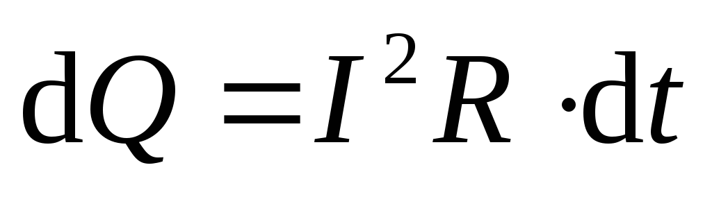
Let's tie it up effective value current with its amplitude value. To do this, let's calculate the amount of heat generated at the active resistance by alternating current in a time equal to the oscillation period. Let us recall that according to the Joule-Lenz law, the amount of heat released in a section of the circuit with resistance permanent current  during
  , is determined by the formula
 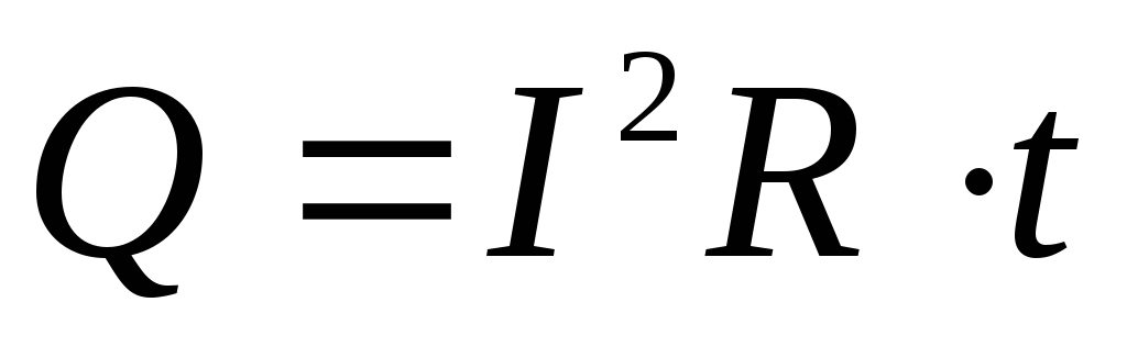 . Alternating current can be considered constant only for very short periods of time
 ![]() . Let's divide the oscillation period
. Let's divide the oscillation period  for a very large number of small periods of time
 ![]() . Quantity of heat
. Quantity of heat  , allocated at the resistance
  during
 ![]() :
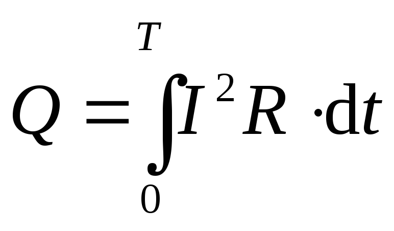
: . The total amount of heat released over a period can be found by summing up the heat released over individual short periods of time, or, in other words, by integrating:
 .
.
The current strength in the circuit varies according to a sinusoidal law
 ,
,
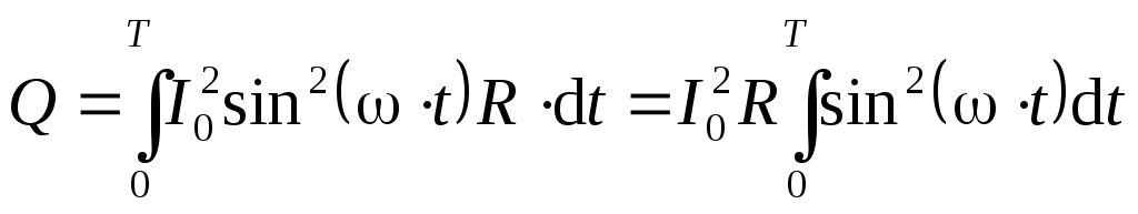 .
.
Omitting the calculations associated with integration, we write the final result
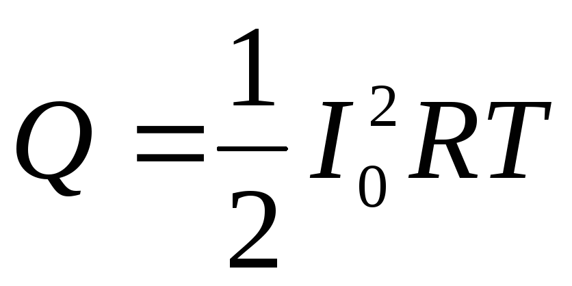 .
.
If some direct current flowed through the circuit , then in a time equal to , heat would be released  . By definition, direct current , which has the same thermal effect as alternating current, will be equal to the effective value of alternating current
  . We find the effective value of the current by equating the heat released over a period in the cases of direct and alternating currents
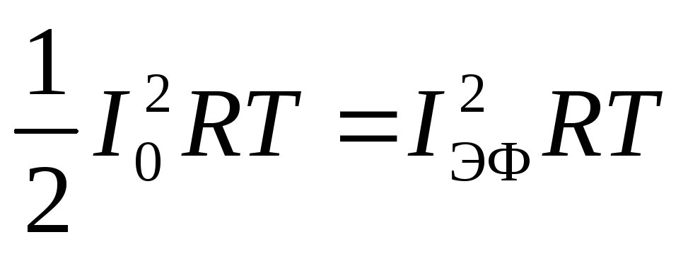
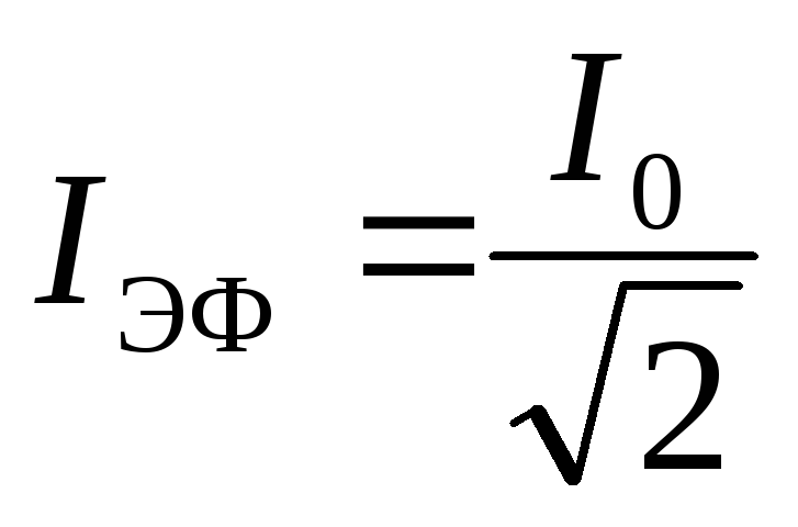 (4.28)
Obviously, exactly the same relationship connects the effective and amplitude values of the voltage in the circuit with the sinusoidal alternating current:
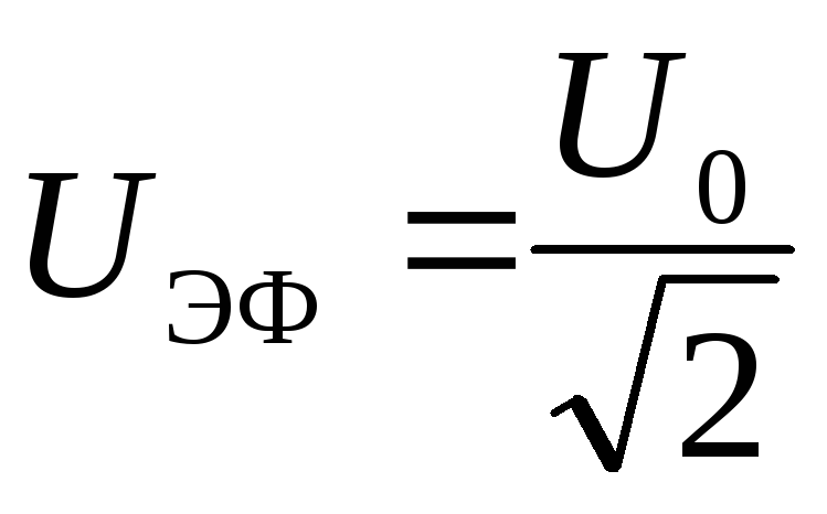 (4.29)
For example, the standard network voltage of 220 V is the effective voltage. Using formula (4.29), it is easy to calculate that the amplitude value of the voltage in this case will be equal to 311 V.
4.4.5. AC power
Let in some section of the circuit with alternating current the phase shift between current and voltage be equal to  , i.e. Current and voltage change according to the laws:
, .
.
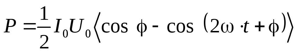
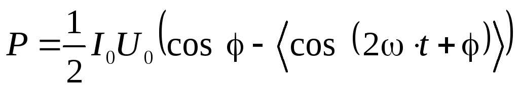
Then the instantaneous value of the power released in the circuit section is
Power changes over time. Therefore, we can only talk about its average value. Let us determine the average power released over a fairly long period of time (many times longer than the oscillation period):
Using the well-known trigonometric formula
 .
.
Size  there is no need to average, since it does not depend on time, therefore:
 .
.
Over a long period of time, the value of the cosine manages to change many times, taking on both negative and positive values ranging from (1) to 1. It is clear that the average value of the cosine over time is zero
 , That's why
 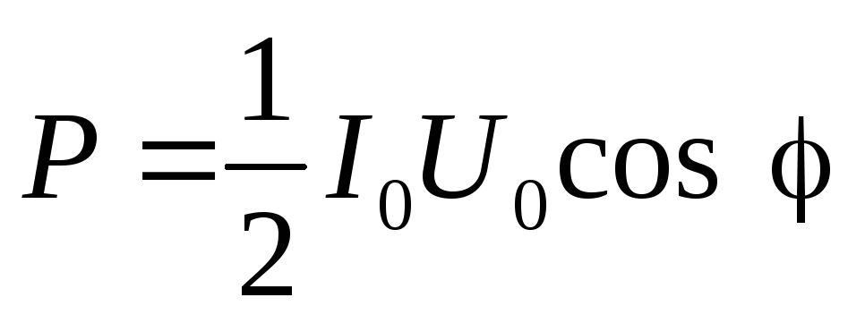 (4.30)
Expressing the amplitudes of current and voltage through their effective values using formulas (4.28) and (4.29), we obtain
 . (4.31)
The power released in the AC section of the circuit depends on the effective values of current and voltage and phase shift between current and voltage. For example, if a section of a circuit consists of only active resistance, then  And
And  . If a section of a circuit contains only inductance or only capacitance, then
 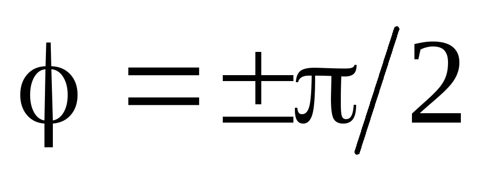 And
And  .
.
The average zero value of power allocated to inductance and capacitance can be explained as follows. Inductance and capacitance only borrow energy from the generator and then return it back. The capacitor charges and then discharges. The current strength in the coil increases, then drops again to zero, etc. It is for the reason that the average energy consumed by the generator at inductive and capacitive reactances is zero, they were called reactive. At active resistance, the average power is different from zero. In other words, a wire with resistance When current flows through it, it heats up. And the energy released in the form of heat does not return back to the generator.
If a section of the circuit contains several elements, then the phase shift may be different. For example, in the case of the circuit section shown in Fig. 4.5, the phase shift between current and voltage is determined by formula (4.27).
Example 4.7. A resistor with resistance is connected to the alternating sinusoidal current generator . How many times will the average power consumed by the generator change if a coil with inductive reactance is connected to a resistor?  a) in series, b) in parallel (Fig. 4.10)? Neglect the active resistance of the coil.
Solution. When only active resistance is connected to the generator , power consumption
 (see formula (4.30)).
Consider the circuit in Fig. 4.10, a. In example 4.6, the amplitude value of the generator current was determined:  . From the vector diagram in Fig. 4.11,a we determine the phase shift between the current and voltage of the generator

 .
.
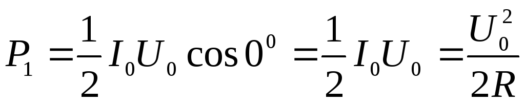
As a result, the average power consumed by the generator
 .
.
Answer: when connected in series to an inductance circuit average power, consumed by the generator, will decrease by 2 times.
Consider the circuit in Fig. 4.10, b. In example 4.6, the amplitude value of the generator current was determined  . From the vector diagram in Fig. 4.11b we determine the phase shift between the current and voltage of the generator
 .
.
Then the average power consumed by the generator
Answer: when inductance is connected in parallel, the average power consumed by the generator does not change.
As is known, variable emf. Induction causes alternating current in a circuit. At the highest value of emf. the current will have a maximum value and vice versa. This phenomenon is called phase matching. Although current values can fluctuate from zero to a certain maximum value, there are instruments with which you can measure the strength of alternating current.
The characteristic of alternating current can be actions that do not depend on the direction of the current and can be the same as with direct current. These actions include thermal action. For example, alternating current flows through a conductor with a given resistance. After a certain period of time, a certain amount of heat will be released in this conductor. It is possible to select a value of direct current such that the same amount of heat is generated on the same conductor during the same time by this current as with alternating current. This value of direct current is called the effective value of alternating current.
Currently, it is widely used in global industrial practice. three phase alternating current, which has many advantages over single-phase current. A three-phase system is called a system that has three electrical circuits with their own variable emfs. with the same amplitudes and frequency, but shifted in phase relative to each other by 120° or 1/3 of the period. Each such chain is called phase.
To obtain a three-phase system, you need to take three identical single-phase alternating current generators and connect their rotors to each other so that they do not change their position when rotating. The stator windings of these generators must be rotated relative to each other by 120° in the direction of rotor rotation. An example of such a system is shown in Fig. 3.4.b.
According to the above conditions, it turns out that the emf arising in the second generator will not have time to change compared to the emf. the first generator, i.e. it will be delayed by 120°. E.m.f. the third generator will also be delayed in relation to the second by 120°.
However, this method of producing alternating three-phase current is very cumbersome and economically unprofitable. To simplify the task, you need to combine all the stator windings of the generators in one housing. Such a generator is called a three-phase current generator (Fig. 3.4.a). When the rotor begins to rotate, a

a) b)
Rice. 3.4. Example of a three-phase AC system
a) three-phase current generator; b) with three generators;
changing e.m.f. induction. Due to the fact that the windings shift in space, the oscillation phases in them also shift relative to each other by 120°.
In order to connect a three-phase alternator to a circuit, you need to have 6 wires. To reduce the number of wires, the windings of the generator and receivers need to be connected to each other, forming a three-phase system. There are two types of connections: star and triangle. When using both methods, you can save electrical wiring.
Star connection
Typically, a three-phase current generator is depicted as 3 stator windings, which are located at an angle of 120° to each other. The beginnings of the windings are usually designated by letters A, B, C, and the ends - X, Y, Z. In the case when the ends of the stator windings are connected to one common point (zero point of the generator), the connection method is called “star”. In this case, wires called linear are connected to the beginnings of the windings (Fig. 3.5 on the left).

Receivers can be connected in the same way (Fig. 3.5., right). In this case, the wire that connects the zero point of the generator and receivers is called zero. This three-phase current system has two different voltages: between the line and neutral wires or, what is the same, between the beginning and end of any stator winding. This value is called phase voltage ( Ul). Since the circuit is three-phase, the line voltage will be v3 times more than phase, i.e.: Ul = v3Uф.
Delta connection.
 Figure 3.6. Example of a triangle connection
When using this connection method, the end X the first winding of the generator is connected to the beginning IN its second winding, end Y second winding - to the beginning WITH third winding, end Z third winding - to the beginning A first winding. An example of a connection is shown in Fig. 3.6. At this method connecting phase windings and connecting a three-phase generator to a three-wire line, the linear voltage in its value is compared with the phase voltage: Uф = Uл
1. List the main parameters characterizing alternating current.
2. Give the definition of frequency and its unit of measurement.
3. Define amplitude and its unit of measurement.
4. Define a period and its units of measurement.
5. The difference between the simplest three-phase current generator and a single-phase current generator.
6. What is a phase?
7. What is the rotor of a three-phase current generator?
8. Why are the stator windings of a three-phase current generator shifted in phase?
9. Feature of a symmetrical three-phase system.
10. The principle of connecting the phase windings of three-phase generators and transformers according to the “star” circuit.
11. The principle of connecting the phase windings of three-phase generators and transformers according to the “triangle” diagram.
3.2. Types of resistance in alternating current circuits
In alternating current circuits, resistances are divided into active and reactive.
IN active resistances , included in the alternating current circuit, electrical energy is converted into thermal energy. Active resistance R possess, for example, wires of electrical lines, windings of electrical machines, etc.
IN reactance the electrical energy generated by the source is not consumed. When reactance is included in an alternating current circuit, only energy exchange occurs between it and the source electrical energy. Reactance is created by inductance and capacitance.
If we do not take into account the mutual influence of individual elements electrical circuit, then in the general case the electrical circuit of sinusoidal current can be represented by three passive elements: active resistance R, inductance L and capacitance C.
Active resistance in the AC circuit.
When an active resistance is connected to an alternating current circuit, the current and voltage are in phase (Fig. 3.7) and change according to the same sinusoidal law: u=U m sinωt. They achieve their goals at the same time maximum values and simultaneously pass through zero (Fig. 3.7.b).
For an alternating current circuit containing only active resistance, Ohm's law has the same form as for a direct current circuit: I=U/R.
Electric power R in a circuit with active resistance at any time is equal to the product of the instantaneous current values i and voltage u: p=ui.
Figure 3.7. Scheme for connecting active resistance R (a) to an alternating current circuit, current curves i, voltage u and power p(b) and vector diagram.
It can be seen from the graph that the power change occurs at double the frequency with respect to the change in current and voltage, i.e. one period of power change corresponds to half the period of current and voltage change. All power values are positive, which means that energy is transferred from the source to the consumer.
Average power Pcp, consumed by active resistance, P=UI=I 2 R- That's what it is active power.
Under inductance L we will understand an element of an electrical circuit (an inductor, the losses of which can be neglected), capable of storing energy in its magnetic field, which has no active resistance and capacitance WITH ( Fig.3.8).
When an inductance is connected to an alternating current circuit, the changing current continuously induces an emf in it. self-induction e L = LΔi/Δt, Where Δi/Δt– rate of change of current.
When the angle ωt equal to 90° and 270° rate of change of current Δi/Δt=0, so e.m.f. e L=0.
The rate of change of current will be greatest when the angle ωt equals 0°, 180° and 360°. At these minutes of time, the emf. It has highest value.
The power curve is a sine wave that varies at twice the frequency of current and voltage. Power has positive and negative values, i.e. a continuous oscillatory process of energy exchange occurs between the source and the inductance.
Figure 3.8. Scheme for connecting inductance (a) to an alternating current circuit, current curves i, voltage u, e.m.f. e L(b) and vector diagram (c)
E.m.f. self-induction according to Lenz's rule is directed so as to prevent a change in current. In the first quarter of the period, when the current increases, the emf. It has negative meaning(directed against the current).
In the second quarter of the period, when the current decreases, the emf. has a positive value (coincident in direction with the current).
In the third quarter of the period, the current changes its direction and increases, so the emf. is directed against the current and has a positive value.
In the fourth quarter of the period, the current decreases and the emf decreases. self-induction tends to maintain the previous position of the current and has a negative value. As a result, the current lags behind the voltage in phase by an angle of 90 O.
The resistance of a coil or conductor to alternating current caused by the action of emf. self-induction is called inductive reactance X L[Ohm]. Inductive reactance is independent of the coil material and the cross-sectional area of the conductor.
In AC circuits, inductors are connected in series and in parallel.
When the coils are connected in series, the equivalent inductance is Le and equivalent inductive reactance X L e will be equal:
Le=L 1 +L 2 +… X L e=X L 1 +X L 2 +…
When connecting coils in parallel:
1/Le=1/L 1 +1/L 2 +… 1/X L e=1/X L 1 +1/X L 2 +…
Control questions
1. What types of resistance in alternating current circuits do you know?
2. What does active resistance mean?
3. What is reactance?
4. What circuit elements create reactance?
5. What is active power?
1. Define inductance.
2. What happens in the first quarter of the period of the oscillatory process of energy exchange between the source and the inductance?
3. What happens in the second quarter of the period of the oscillatory process of energy exchange between the source and the inductance?
4. Define inductive reactance.
3.3. Capacitors. Capacitance in AC circuit
Capacitor – a device capable of storing electrical charges.
The simplest capacitor consists of two metal plates(electrodes) separated by a dielectric.
Each capacitor is characterized by a nominal capacitance and permissible voltage. The capacitor voltage is indicated on the housing and must not be exceeded. Capacitors differ in the shape of the electrodes (flat), the type of dielectric and the capacitance (constant and variable).
Page 2
The effective value of current strength I is the strength of direct current that releases in the conductor during the same time the same amount of heat as alternating current.
As can be seen from the figure, at each moment of time the voltage and current values take on different values. Therefore, to judge the magnitude of current and voltage of alternating current, use the effective value of current and voltage. To determine the effective value of the alternating current, it is equated to the direct current, which would release the same amount of heat in the conductor as alternating current.
A transformer containing 300 turns in the primary winding is connected to an alternating current network with an operating voltage of 220 V. The secondary circuit of the transformer supplies a load with an active resistance of 50 Ohms. Find the effective value of the current in the secondary circuit if the voltage drop in the secondary winding of the transformer, containing 165 turns, is 50 V.
Thus, when replacing the operation of extracting the root with a comparison, the time during which the integrated signal with GLIN becomes equal to the integral of the square of the measured current strength, proportional to the effective value of the current strength. Before this, K2 was open for time t and passed pulses from the GTI clock pulse generator to the SI counter. The number of pulses TV/gtit recorded in the midrange is proportional to the effective current value. This number is stored in / 77, and at the end of the measurement cycle is displayed on the DRO.
As with mechanical vibrations, in the case of electrical vibrations we are usually not interested in the values of current, voltage and other quantities at each moment in time. Important General characteristics oscillations, such as amplitude, period, frequency, effective values of current and voltage and average power. It is the effective values of current and voltage that are recorded by ammeters and alternating current voltmeters.
Рх o jjFr In the case of a t - n - DRY lamp, use the method of a thermometer suspended near the generator lamp, and note its reading. Then, breaking the circuit of the oscillatory circuit of the generator, they give a positive potential to the grid of the generator lamp until the thermometer reaches the temperature. In the latter case, taking the values 1a and Ea as initial, we determine Px from the relation Px1a Ea. The power in the antenna is determined by the formula Px - / /, where РЯ is the power eW, ra is the active resistance of the antenna in Q and 1a is the effective value of the current in the antenna in A. Since, according to modern international standards, transmitter power is usually understood as power in the antenna, then the above-mentioned f-la simultaneously determines the power of the transmitter.
Thermal meters have the widest practical range. Thermal meters operate by elongating a thin wire when it is heated by a high-frequency alternating current passing through it. The effect itself limits the applicability of such meters to currents from several tA to 1 - 3 A, depending on the material of the thin wire used in the meter. Alloys of silver with platinum, platinum with iridium, etc. are used. If the alloy is used in the form of wire, then it has a diameter of hundredths of a mm. With tape, the thickness is 0 01 mm, width 3 mm and length 25 - 30 mm. The elongation of the filament by a heated current is proportional to the square of the effective value of the current. The movement of a pointer on the meter scale, connected to the same wire using a special movable system, is usually proportional square root from acting force current Because of this, the scales of thermal meters have uneven intervals between divisions.
IN in this case Current oscillations are harmonic (oscillation graph - sinusoid) and forced, since the oscillation parameters (frequency, amplitude) are determined by an external source - a generator. Some electrical devices (for example, an oscillating circuit) are capable of generating free harmonic oscillations electric current. Along the left branch of the frame - away from us and, since in this case current flows through terminal a in the direction opposite to that shown in Fig. 12.1, its polarity is minus. Since at a given position of the frame the current strength is greatest, the oscillation phase can be r / 2 or 3 / 2ir, depending on which direction of the current in the frame we take to be positive. Comparing formula (12.1) and the given dependence, it is easy to notice that 1t 10 A and w 4tgrad / s. Next, using formula (12.2), we determine the oscillation frequency (resp. Using the Joule-Lenz law (Q I2Rt), we determine the effective value of the current strength (resp.