LED reverse voltage. How to connect an LED to a lighting network
Typically, LEDs are connected to 220V using a driver designed for their characteristics. But if you need to connect only one low-power LED, for example, as an indicator, then using a driver becomes impractical. In such cases, the question arises - how to connect the LED to 220 V without an additional power supply.
NEW!!! LED 3D LIGHTS - There is always a place for magic in life...Basics of connecting to 220 V
Unlike, which powers the LED with direct current and a relatively low voltage (a few to tens of volts), the network produces an alternating sinusoidal voltage with a frequency of 50 Hz and an average value of 220 V. Since the LED passes current only in one direction, it will only glow in certain half-waves:
That is, the LED does not glow constantly with this power supply, but blinks at a frequency of 50 Hz. But due to the inertia of human vision, this is not so noticeable.
At the same time, a voltage of reverse polarity, although it does not cause the LED to glow, is still applied to it and can damage it if no protective measures are taken.
Methods for connecting an LED to a 220 V network
The easiest way (read about all the possible ones) is to connect using a quenching resistor connected in series with the LED. It should be taken into account that 220 V is the rms value of U in the network. The amplitude value is 310 V, and must be taken into account when calculating the resistance of the resistor.
In addition, it is necessary to protect the light-emitting diode from reverse voltage of the same magnitude. This can be done in several ways.
Series connection of a diode with a high reverse breakdown voltage (400 V or more).
Let's look at the connection diagram in more detail.
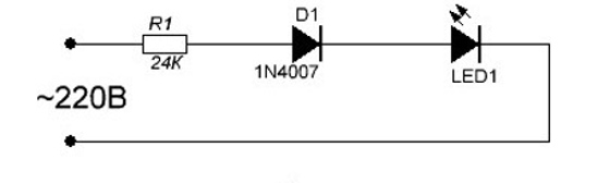
The circuit uses rectifier diode 1N4007 with a reverse voltage of 1000 V. When the polarity is changed, all the voltage will be applied to it, and the led will be protected from breakdown.
This connection option is clearly shown in this video:
It also describes how to calculate the resistance of the quenching resistor for a standard low-power LED.
Bypassing an LED with a conventional diode.
Any low-power diode connected back-to-back with the LED will do here. In this case, the reverse voltage will be applied to the quenching resistor, because the diode turns on in the forward direction.

Back-to-back connection of two LEDs:
The connection diagram looks like this:
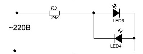
The principle is similar to the previous one, only here the light-emitting diodes each burn in their own section of the sinusoid, protecting each other from breakdown.
Please note that connecting an LED to a 220V power supply without protection leads to its rapid failure.
Schemes for connecting to 220V using a quenching resistor have one serious drawback: a large amount of power is released at the resistor.
For example, in the cases considered, a resistor with a resistance of 24 Kom is used, which at a voltage of 220 V provides a current of about 9 mA. Thus, the power dissipated by the resistor is:
9 * 9 * 24 = 1944 mW, approximately 2 W.
That is, for optimal operation you will need a resistor with a power of at least 3 W.
If there are several LEDs, and they consume more current, then the power will increase in proportion to the square of the current, which will make the use of a resistor impractical.
The use of a resistor of insufficient power leads to its rapid overheating and failure, which can cause a short circuit in the network.
In such cases, a capacitor can be used as a current-limiting element. The advantage of this method is that no power is dissipated on the capacitor, since its resistance is reactive.
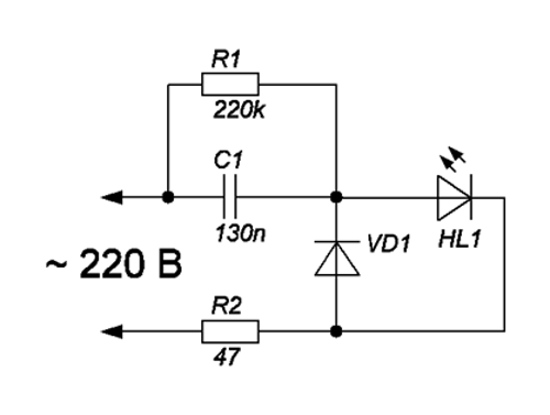
Shown here typical diagram connecting a light-emitting diode to a 220V network using a capacitor. Since the capacitor, after turning off the power, can retain a residual charge that is dangerous to humans, it must be discharged using resistor R1. R2 protects the entire circuit from current surges through the capacitor when the power is turned on. VD1 protects the LED from reverse polarity voltage.
The capacitor must be non-polar, designed for a voltage of at least 400 V.
The use of polar capacitors (electrolyte, tantalum) in an alternating current network is unacceptable, because current passing through them in the opposite direction destroys their structure.
The capacitor capacity is calculated using the empirical formula:
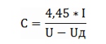
where U is the amplitude voltage of the network (310 V),
I – current passing through the LED (in milliamps),
Ud – voltage drop across the led in the forward direction.
Let's say you need to connect an LED with a voltage drop of 2 V at a current of 9 mA. Based on this, we calculate the capacitance of the capacitor when connecting one such LED to the network:
This formula is only valid for a network voltage fluctuation frequency of 50 Hz. At other frequencies, a recalculation of the factor 4.45 will be required.
The nuances of connecting to a 220 V network
When connecting an LED to a 220V network, there are some features related to the amount of current passing. For example, in common backlit light switches, the LED is turned on according to the circuit shown below:
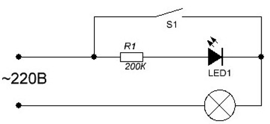
As you can see, there are no protective diodes here, and the resistor value is chosen in such a way as to limit the forward current of the LED to about 1 mA. The lamp load also serves as a current limiter. With this connection scheme, the LED will glow dimly, but enough to see the switch in the room at night. In addition, the reverse voltage will be applied mainly to the resistor when the switch is open, and the light-emitting diode will be protected from breakdown.
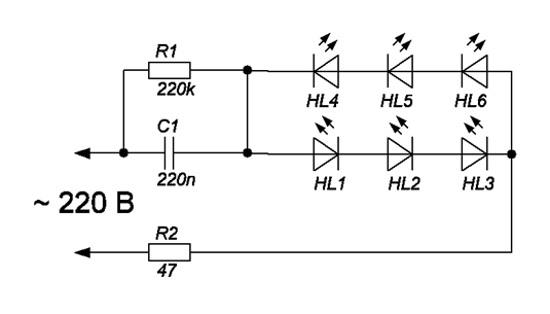
If you need to connect several LEDs to 220V, you can turn them on in series based on a circuit with a quenching capacitor:
![]()
In this case, all LEDs must be designed for the same current for uniform illumination.
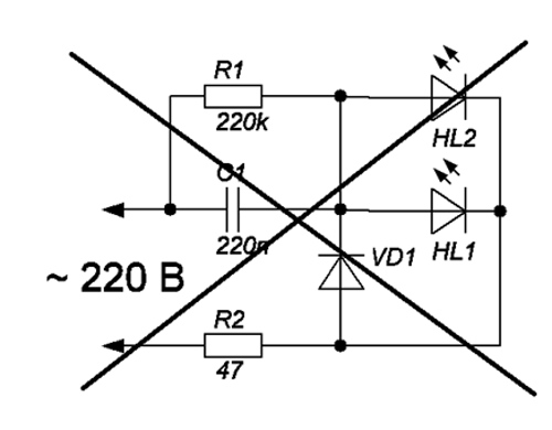
You can replace the bypass diode with a back-to-back LED connection:
Parallel (not back-to-back) LED connection into the network is unacceptable, since if one circuit fails, double the current will flow through the other, which will cause the LEDs to burn out and a subsequent short circuit.
Several more options for the unacceptable connection of light-emitting diodes to a 220V network are described in this video:
Here's why you can't:
- turn on the LED directly;
- connect LEDs designed for different currents in series;
- turn on LED without reverse voltage protection.
Connection security
When connecting to 220V, it should be taken into account that the light switch usually opens the phase wire. Zero in this case is carried out common throughout the room. In addition, the electrical network often does not have a protective ground, so even on the neutral wire there is some voltage relative to the ground. You should also keep in mind that in some cases the ground wire is connected to radiators or water pipes. Therefore, with simultaneous human contact with the phase and battery, especially when installation work in the bathroom, there is a risk of getting under voltage between phase and ground.
In this regard, when connecting to the network, it is better to disconnect both the zero and the phase using a batch machine in order to avoid electric shock when touching live wires of the network.
Conclusion
The methods described here for connecting LEDs to a 220V network are advisable to use only when using low-power light-emitting diodes for illumination or indication purposes. Powerful LEDs cannot be connected this way, since instability of the mains voltage leads to their rapid degradation and failure. In such cases, you need to use specialized LED power supplies - drivers.
One of the important issues when working with LEDs is its connection to an AC and high voltage network. It is known that an LED cannot be powered directly from a 220 V network. How to properly assemble the circuit and provide power to solve the problem?
Electrical properties
To answer the question posed above, it is necessary to study the electrical properties of the LED.
Its current-voltage characteristic is a steep line. This means that when the voltage increases even by a very small amount, the current through the emitting semiconductor increases sharply. An increase in current leads to heating of the LED, as a result of which it may simply burn out. This problem is solved by including a limiting resistor in the circuit.
The LED has a low reverse breakdown voltage (about 20 volts), so it cannot be connected to a 220 volt AC network. To prevent current from flowing in the opposite direction, it is necessary to include a diode in the circuit or turn on a second one opposite the first LED. The connection must be parallel.
So, we know that any circuit for connecting an LED to a 220-volt network must contain a resistor and a rectifier, otherwise power will be impossible.
Why is such a scheme needed? First of all, for the design of the network indicator. An LED light can be an excellent indicator to help determine whether an electrical appliance is plugged in or not. It is added to the circuit of switches and sockets to easily find them in the dark.
Such an indicator begins to glow at a voltage of just a few volts. At the same time, it consumes a minimal amount of electricity due to the low (several miles of amperes) current.
Which resistor should I use?
To select the optimal resistor resistance, you need to use Ohm's law.
R=(Ugrid-Ul.)/Il.nom.
Suppose we took a red LED for the indicator with a nominal current value of 18 mA and a forward voltage of 2.0 Volts.
(311-2)/0.018=17167 Ohm=17 kOhm
Let's explain where the number 311 comes from. This is the peak of a sine wave along which the voltage in our network changes. Without going into the realm of mathematics with all its calculations, we can simply say that the peak voltage is 220 * √2.
Sometimes there are circuits that do not have a rectifying diode. In this case, the resistance must be increased several times in order to reduce the current and protect the indicator light from burning out.
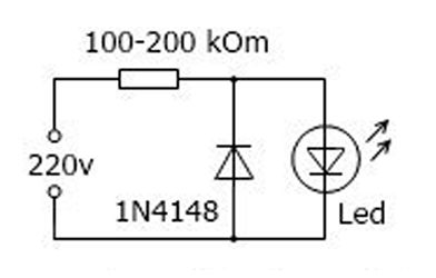
Elementary circuit of a current indicator
What is needed to make the simplest indicator, which is powered from a 220 volt network? Here is the list:
- a regular indicator LED of any color you like;
- resistor from 100 to 200 kOhm (the higher the resistance, the less brightly the light bulb will glow);
- diode with a reverse voltage of 100 volts or more;
- low-power soldering iron so as not to overheat the LED.
Since the number of parts is minimal, the board is not used in installation. The indicator is connected in parallel to the electrical appliance.
For those who do not want to run around looking for a diode, manufacturers have come up with a ready-made two-color indicator in the form of two LEDs of different colors built into one housing. Usually these colors are red and green. In this case, the number of circuit parts is further reduced.
There are other connection schemes in which the resistor is replaced with a capacitor or diode bridges, transistors, etc. are used. But no matter what design features were not introduced, the main task is to rectify the current and reduce it to a safe value.
In decorative lighting and other places where the LED is used as a light source, it is customary to connect it through a driver. The driver already has the necessary parameters for uninterrupted and maximum efficient operation of the LED. It is relevant in cases where the circuit contains several powerful crystals or a whole set of LED strips.
Connecting the LED directly to a voltage of 220 V is used in the case when the LED will look like a weak indicator - if one or more elements are involved in the connection. For them, buying a driver is completely impractical. This material describes the difference between connecting via a driver and connecting to a 220 V network directly, and also shows and explains connection diagrams of various types.
What is the connection difference?
How to connect an LED to a 220 V network? The problem initially lies in technical specifications LED. Its work is based on passing a certain current through the crystals, as a result of which they shine. The driver is designed to control the supply of current to the crystal, limiting it to the amount that is necessary specifically for these models of connected LEDs.
Driver connection example
for decorative lighting with LEDs
The key feature of the driver is the supply to the LED direct current, and not alternating current, which flows in a regular household outlet. 220 V alternating current supplies the crystals with a sine-like voltage with a frequency of 50 Hz. This means that its direction changes 50 times per second. Moreover, if you turn on the LED, it will glow only when the main current is supplied and go out when the current is reversed. In the diagram it looks like this.
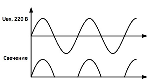
Dependence of crystal glow
from the direction of alternating current
Looking at the graph, it becomes clear that the LED will not shine constantly, but will blink at the same frequency as the current itself - 50 times per minute. For the human eye, such flickering is not discernible, and it will see ordinary uniform light. But this does not mean that the LED is connected to the network correctly.
An LED is capable of passing current only in one direction; reverse oscillations lead to destruction of its structure and subsequent degradation. To ensure that the LED does not fail, protective measures must be applied to it.
AC Connection Methods
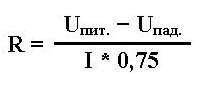
Resistor value A simple and cheap way is to use a quenching resistor, which is included in the electrical circuit, which is a series connection of LEDs. The rated power of the limiting resistor will be the value calculated using the following formula:
where: 0.75 – LED reliability coefficient (theoretical, ask the manufacturer for specifics);
Upit – current source voltage;
Upad is the voltage that drops across the diode and causes the crystal to glow;
I – rated through current.
At the same time, remember that the voltage of the current source should be taken not as 220 V, but as an amplitude parameter of 310 V. This must be taken into account for the correctness of the output parameters when performing the calculation.
![]()
After connecting the resistor to the circuit, a fairly strong resistance appears, which is accompanied by a noticeable release of heat - after all, the falling voltage must be converted somewhere. Therefore, an important parameter when selecting a resistor is its power, which is calculated using the formula:
where: U – difference between mains and drop voltages.
Connecting a resistor, made by yourself, will smooth out the sharp amplitude of the alternating current and allow you to connect the LEDs to a 220-volt network. But even after connecting it, there is still a reverse voltage of the same strength, so several more operations are performed to ensure the safety of the crystal.
Connecting a diode with a high reverse breakdown threshold. This is the simplest and effective method Protect LEDs from reverse current. The point is that this diode has a colossal resistance in the opposite direction, passing current in one direction and preventing it from passing in the other. In the diagram it looks like this:

There is no need to perform a calculation here - the reverse voltage of such a diode must exceed the 310 V indicated above. When the direction of the current changes, the entire voltage will be applied only to it. Practice shows that the greater its resistance, the more reliably it will protect the LED. The optimal parameter approaches 1,000 V.
Back-to-back connection of an LED and a conventional diode. Unlike a freewheeling diode, a resistor cancels the voltage in both directions. Meaning this method is to direct the reverse amplitude directly to a previously installed resistor, which will dampen it. Please note that for such a circuit, the previously calculated resistor parameters need to be at least doubled and a small tail of 5–10% added to absorb voltage drops.

The last two methods are very economical in terms of purchasing and installing radio components, but they have a common significant disadvantage - with double resistance across the resistor, double heat generation is generated. Therefore, it is necessary to correctly calculate its power. Let's imagine the most simple ways perform the calculation. Let's assume that our circuits used resistors with a resistance of 30 kOhm; at an alternating voltage of 220 V, they produce a current of about 10 mA. We calculate how much heat is generated on the element:
10×10×30 = 3,000 mW or 3 W.
It follows from this that for normal operation of a resistor in a circuit with two LEDs, its power should approach 4 W - this margin is quite enough for safe operation.
The following problem arises - increasing the number of LEDs powered from the network in the circuit, even up to 3 pieces, leads to enormous demands on the resistor - its power should already be approaching 40 W, which is not economically and logically profitable at all. This nuance should not be neglected - if the power is not enough to generate such heat, the resistor will very quickly overheat and burn out, causing a dangerous short circuit in the network and causing many problems.
Connecting a capacitor to an electrical circuit. This type of load has a great advantage over a resistor - its resistance is reactive, that is, power is not dissipated on it. Below is the most common diagram for connecting LEDs from a 220 V network with a capacitor. It should be remembered that with all its advantages, the capacitor has one significant danger for the user - after turning off the current supply to the 220 V network, it continues to store residual charges inside. To neutralize them, resistor R1 is connected to the circuit. Resistor R2 is installed to protect the circuit from a sudden voltage surge across the capacitor. We also do not forget about installing a reverse voltage diode VD1, which protects the LED from reverse polarity.
Let's also mention the load material. It comes in two types - polar and non-polar. For our circuit, only volt non-polar options are mandatory. It is prohibited to install electrolytic and tantalum ones - reverse voltage will very quickly destroy their structure, which will lead to circuit burnout and short circuit. Its power is similar to a resistor for these purposes - at least 400 V.

The capacitor has a parameter that needs to be calculated before connecting the LEDs to a 220 volt network - capacitance. The empirical formula is given below:
where: U – the same amplitude AC voltage, 310 V;
I – current that passes through the installed LED, mA;
Ud – falling current voltage to form a glow on the crystal.
Use in everyday life
Most often, such schemes are found in. Typical scheme correct use listed below:

Due to the low power of lighting devices, they do not have protective reverse diodes. The resistor is set to limit the forward current to 1 mA. This scheme for connecting an LED to a 220-volt network is not particularly effective in terms of the brightness of the glow, it is very dim, but it plays its role well - in a dark room the switch is visible. Here, the reverse voltage when the circuit contacts are opened is directed to a resistor; the presence of an LED or any other light bulb, as well as a power supply, also acts as an additional load. Thus, the LED is protected from reverse current breakdown.
Safety precautions
Briefly about the nuances of connection, which is performed in most homes - to ensure safety when working with electrical circuit Often it is not enough to turn off just one switch. The fact is that it, as a rule, opens the phase, but due to the lack of grounding, a residual voltage remains at zero. If the grounding is incorrect, for example, people connect to a battery or water supply, there is a risk of getting voltage between the phase and ground. Turn off the power completely at the switch or meter at the entrance to the house or apartment, and make proper grounding if you do not have one.
Conclusion
In creating such a circuit, the main nuance is the correct selection of resistor and capacitor parameters. The alternating current that flows in the outlet has a strong destructive effect on elements that are not adapted to pass reverse current through themselves. Proper limitation of the amplitude of alternating current with a given depreciation reserve and correct calculation will protect the circuit from burnout and short circuit, allowing it to work long and reliably.
After reading this title, someone may ask: “Why?” Yes, if you just plug it into a socket, even if you turn it on according to a certain scheme, it has no practical significance, no useful information won't bring it. But if the same LED is connected in parallel to a heating element controlled by a thermostat, then you can visually monitor the operation of the entire device. Sometimes such an indication allows you to get rid of many minor problems and troubles.
In light of what has already been said, the task seems trivial: just install a limiting resistor of the required value, and the issue is resolved. But all this is good if you power the LED rectified constant voltage: as soon as the LED was connected in the forward direction, it remained so.
When working on alternating voltage, everything is not so simple. The fact is that, in addition to direct voltage, the LED will also be affected by reverse polarity voltage, because each half-cycle of the sine wave changes sign to the opposite one. This reverse voltage will not illuminate the LED, but it can render it unusable very quickly. Therefore, it is necessary to take measures to protect against this “harmful” voltage.
In the case of mains voltage, the calculation of the quenching resistor should be based on a voltage value of 310V. Why? Everything is very simple here: 220V is , the amplitude value will be 220 * 1.41 = 310V. The amplitude voltage is two (1.41) times the root voltage, and this should not be forgotten. This is the forward and reverse voltage that will be applied to the LED. It is from the value of 310V that the resistance of the quenching resistor should be calculated, and it is from this voltage, only with reverse polarity, that the LED should be protected.
How to protect an LED from reverse voltage
For almost all LEDs, the reverse voltage does not exceed 20V, because no one was going to make a high-voltage rectifier for them. How to get rid of such a scourge, how to protect the LED from this reverse voltage?
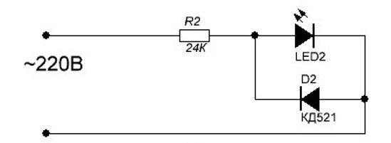
It turns out that everything is very simple. The first way is to connect a regular one in series with the LED with a high reverse voltage (not lower than 400V), for example, 1N4007 - reverse voltage 1000V, forward current 1A. He's the one who won't miss high voltage negative polarity to the LED. The diagram of such protection is shown in Fig. 1a.
The second method, no less effective, is to simply bypass the LED with another diode connected back-to-back - in parallel, Fig. 1b. With this method protection diode It doesn’t even have to be with a high reverse voltage; any low-power diode, for example, KD521, is enough.
Moreover, you can simply turn on two LEDs in parallel: opening alternately, they will protect each other, and both will emit light, as shown in Figure 1c. This is already the third method of protection. All three protection schemes are shown in Figure 1.
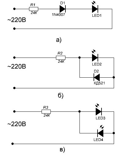
Figure 1. LED reverse voltage protection circuits
The limiting resistor in these circuits has a resistance of 24KOhm, which, at an operating voltage of 220V, provides a current of the order of 220/24 = 9.16 mA, which can be rounded to 9. Then the power of the quenching resistor will be 9 * 9 * 24 = 1944 mW, almost two watts. This despite the fact that the current through the LED is limited to 9mA. But long-term use of a resistor at maximum power will not lead to anything good: first it will turn black and then completely burn out. To prevent this from happening, it is recommended to install two 12KΩ resistors in series with a power of 2W each.
If we set the current level to 20mA, then the resistor power will be even greater - 20*20*12=4800mW, almost 5W! Naturally, no one can afford a stove of such power to heat a room. This is based on one LED, but what if there is a whole one?
Capacitor - wattless resistance
The circuit shown in Figure 1a uses protective diode D1 to “cut off” the negative half-cycle of the alternating voltage, therefore the power of the quenching resistor is halved. But still, the power remains very significant. Therefore, it is often used as a limiting resistor: it will limit the current no worse than a resistor, but it will not generate heat. It is not without reason that a capacitor is often called a wattless resistance. This switching method is shown in Figure 2.
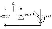
Figure 2. Circuit for connecting an LED through a ballast capacitor
Everything seems to be fine here, there is even a protective diode VD1. But two details are not provided. First, capacitor C1, after turning off the circuit, can remain charged and store a charge until someone discharges it with their own hand. And this, believe me, will definitely happen someday. The electric shock is, of course, not fatal, but quite sensitive, unexpected and unpleasant.
Therefore, in order to avoid such a nuisance, these quenching capacitors are bypassed with a resistor with a resistance of 200...1000KOhm. The same protection is established in transformerless units power supply with a quenching capacitor, in optocouplers and some other circuits. In Figure 3 this resistor is designated R1.
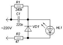
Figure 3. Diagram of connecting an LED to a lighting network
In addition to resistor R1, resistor R2 also appears on the diagram. Its purpose is to limit the surge of current through the capacitor when voltage is applied, which helps protect not only the diodes, but also the capacitor itself. It is known from practice that in the absence of such a resistor, the capacitor sometimes breaks, its capacity becomes much less than the nominal one. Needless to say, the capacitor must be ceramic for an operating voltage of at least 400V or special for operation in alternating current circuits for a voltage of 250V.
Resistor R2 plays another important role: in the event of a breakdown of the capacitor, it acts as a fuse. Of course, the LEDs will also have to be replaced, but at least the connecting wires will remain intact. In fact, this is exactly how a fuse works in any device - the transistors burned out, and printed circuit board remained almost untouched.
The diagram shown in Figure 3 shows only one LED, although in fact several of them can be connected in series. The protective diode will cope with its task alone, but the capacitance of the ballast capacitor will have to be calculated, at least approximately, but still.
In order to calculate the resistance of the quenching resistor, it is necessary to subtract the voltage drop across the LED from the supply voltage. If several LEDs are connected in series, then simply add their voltages and also subtract them from the supply voltage. Knowing this residual voltage and the required current, it is very simple to calculate the resistance of the resistor according to Ohm’s law: R=(U-Uд)/I*0.75.
Here U is the supply voltage, Ud is the voltage drop across the LEDs (if the LEDs are connected in series, then Ud is the sum of the voltage drops across all LEDs), I is the current through the LEDs, R is the resistance of the quenching resistor. Here, as always, the voltage is in Volts, the current is in Amperes, the result is in Ohms, 0.75 is a coefficient for increasing reliability. This formula has already been given in the article.
Forward voltage drop for LEDs different colors different. At a current of 20mA, red LEDs have 1.6...2.03V, yellow 2.1...2.2V, green 2.2...3.5V, blue 2.5...3.7V. White LEDs have the highest voltage drop, having wide range radiation 3.0...3.7V. It is easy to see that the spread of this parameter is quite wide.
Here are the voltage drops of just a few types of LEDs, simply by color. In fact, there are many more of these colors, and the exact meaning can only be found in the technical documentation for a specific LED. But often this is not required: to get a result acceptable for practice, it is enough to substitute some average value (usually 2V) into the formula, of course, if this is not a garland of hundreds of LEDs.
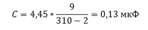
To calculate the capacity of the quenching capacitor, the empirical formula C=(4.45*I)/(U-Ud) is used,
where C is the capacitance of the capacitor in microfarads, I is the current in milliamps, U is the peak voltage of the network in volts. When using a chain of three series-connected white LEDs Ud is approximately 12V, U amplitude voltage of the network is 310V, to limit the current to 20mA you will need a capacitor with a capacity
C=(4.45*I)/(U-Ud)= C=(4.45*20)/(310-12)= 0.29865 µF, almost 0.3 µF.
The closest standard value for capacitor capacitance is 0.15 µF, therefore, to use it in this circuit, you will have to use two parallel-connected capacitors. A remark must be made here: the formula is valid only for an alternating voltage frequency of 50 Hz. For other frequencies the results will be incorrect.
The capacitor must be checked first
Before using the capacitor, it must be tested. To begin with, just turn on the 220V network, preferably through a 3...5A fuse, and after 15 minutes check by touch to see if there is any noticeable heating? If the capacitor is cold, then you can use it. IN otherwise Be sure to take another one and check it first too. After all, 220V is no longer 12V, everything is a little different here!
If this test was successful and the capacitor did not heat up, then you can check whether there was an error in the calculations or whether the capacitor is of the correct capacity. To do this, you need to connect the capacitor to the network as in the previous case, only through an ammeter. Naturally, the ammeter must be AC.
This is a reminder that not all modern digital multimeters can measure alternating current: simple cheap devices, for example, very popular among radio amateurs, are capable of measuring only direct current, but no one knows what such an ammeter will show when measuring alternating current. Most likely it will be the price of firewood or the temperature on the Moon, but not alternating current through a capacitor.
If the measured current is approximately the same as that obtained when calculating using the formula, then you can safely connect the LEDs. If instead of the expected 20...30mA it turns out 2...3A, then there is either an error in the calculations or the capacitor markings were incorrectly read.
Illuminated switches
Here you can focus on another way to include an LED in a lighting network, used in backlit switches. If you disassemble such a switch, you will find that there are no protective diodes there. So, is everything written just above nonsense? Not at all, you just need to take a closer look at the disassembled switch, or more precisely at the resistor value. As a rule, its nominal value is at least 200KOhm, maybe even a little more. In this case, it is obvious that the current through the LED will be limited to about 1mA. The backlit switch circuit is shown in Figure 4.
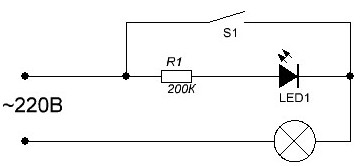
Figure 4. LED connection diagram in a backlit switch
Here, one resistor kills several birds with one stone. Of course, the current through the LED will be small, it will glow weakly, but quite brightly enough to see this glow in the room on a dark night. But during the day this glow is not needed at all! So let yourself shine unnoticed.
In this case, the reverse current will also be weak, so weak that it will in no way burn the LED. Hence the savings of exactly one protective diode, which was described above. When producing millions, and maybe even billions, of switches per year, the savings are considerable.
It would seem that after reading articles about LEDs, all questions about their use are clear and understandable. But there are still many subtleties and nuances when including LEDs in various circuits. For example, parallel and serial connections or, in other words, good and bad circuits.
Sometimes you want to assemble a garland of several dozen LEDs, but how to calculate it? How many LEDs can be connected in series if there is a power supply with a voltage of 12 or 24V? These and other questions will be discussed in the next article, which we will call “Good and bad LED circuits.”
I probably won’t be mistaken if I say that more than 90% of Russian residents know what LED strips, to the question “can transformers from halogen lamps be used to power LED strips?” They will answer “no, you can’t!” The most common explanation will be the banal “electronic transformer is alternating current, but LEDs need constant current.” This is exactly what they tell us in stores, this is exactly the leitmotif of the vast majority of “professional” articles on this topic, which, in general, has taught people to spend significantly more money.
Is this always justified and how do LEDs in the most common LED strips actually behave when powered by alternating current, we will try to find out in the process of reading this article.
I’ll immediately make a reservation that to designate “LED” I will continue to use the self-evident and completely natural abbreviation LED and will deliberately not use the English technical abbreviation LED (Light Emitting Diode) for this concept. In our current country, the lack of any proper technical training of managers and salespeople in stores has already led to littering and the appearance of such unnatural for technical language, foolish to hear and terrible to write letter combinations “leds”, “led'ы”, “ice”, or As I recently saw in a creeping line - “LED light emitting diodes”. Not only is “butter – buttery”, I just don’t want to echo and create this “word confusion”...
The ideological source for writing the study was the long-standing desire to refute unfounded and categorical statements about the inadmissibility of powering LEDs with alternating current. In general, the controversial nature of this statement certainly strikes the eye of any specialist (as well as a “non-specialist”) who understands that an LED, although it emits light, is first and foremost a DIODE. This means that it will still emit under the influence of alternating voltage, but only during its half-cycle.
Essentially, we will need to consistently answer three questions:
1) Will the electric vehicle be able to “start” when connecting a load in the form of semiconductor diodes;2) If the ET starts, will the pulsed “alternating” electrical impact exceed the permissible parameters of the individual LEDs in the tapes. If it does exceed, then how long will the SD last in such conditions;
3) What is economic efficiency from the use of ET in lighting designs on LED strips.
So, six months ago I just had a convenient opportunity to experiment.
I needed to light up the space in the drawers and desk cabinets in my workshop. After equipping the kitchen, I was left with 1.2 meters of single-color LED tape with a total power of about 17 W (Aztech 14 Watt/meter) and one electronic transformer from halogen lamps - EAC 12V 20-60 W, the most common and cheapest, bought for 74 rubles in July 2014. To begin with, to start the ET, I loaded it with an ordinary 20 W halogen lamp and then connected all 1.2 meters of strip in parallel (Fig. 1). As expected, the tape lit up. At the same time, the glow of the tape was uniform, of average brightness, without any flickering noticeable to the eye, which is not surprising, because The output meander of the ET is modulated according to the amplitude, barely noticeable to the eye, at a frequency of 100 Hz. During the experiment, turning off the lamp in such a circuit immediately led to the cessation of the glow of the LED strip, which indicated the impossibility of starting the ET on one half-wave voltage. Then I divided the tape into two sections and turned them on back-to-back (Fig. 2), which, according to the plan, was supposed to ensure the operation of the ET output stage in both half-cycles. At the same time, in order to eliminate the imbalance of currents in the opposite direction and overheating of the output winding of the ET due to the appearance of a constant component, I ensured equality (8 W) in the number of LEDs in both load arms. Immediately after connecting according to this scheme (Fig. 2), the transformer safely entered the generation mode, and both LED strips lit up evenly and were left for 1 hour, during which neither they nor the electric vehicle itself heated up at all, which rather indicated quite normal electrical modes than not.So, the answer to the first question - will the EV start when replacing halogen lamps with LEDs - is positive. Yes, it will start! If you ensure back-to-back connection of the tapes as in Figure 2.
And looking ahead...
Looking ahead, I will say that, as a further experiment showed, an ET with a minimum launch power of 20 W was successfully launched even with a total LED load of 10 W (5 W in each arm).
Go ahead. Now we are trying to find the answer to second question our research. But now experiments alone are not enough for us; we will need knowledge from TERCiE (Theory of Electrical Radio Circuits and Elements), which will ultimately allow us to assume: is it possible to power SD tapes for a long time in this mode without serious damage to their durability, if we talk about damage at all?
Let's start with the SD tape device. The tape consists of working sections connected in parallel (Fig. 3) of three emitters (indicated in the diagram - E) which are three separate LEDs under a common phosphor layer. Each diode (D in the diagram) of the emitter is connected in series in triads with diodes from other emitters and a resistor that sets the calculated operating point of the diodes (See Fig. 4).
The resistor in the triad is selected in such a way that, when powered by 12 V and the calculated operating point of the diode Upr = 3.3 V, Ipr = 14 mA, an excess voltage of about 2 Volts is extinguished on it.
By the way, interesting...
This arrangement of the triad is reliable and practical, because if a single LED in the triad fails, none of the emitters will turn off completely, but will continue to burn, albeit with a third less brightness. You can, of course, create a triad based on a single emitter (and such tapes are available on sale). In them, the working section that determines its cutting will be a fragment with a single emitter and a resistor, but in this case, the failure of a single LED in the triad will lead to the loss of glow by the entire emitter, which will be immediately noticeable in any lamp.
Having rummaged through the manufacturers SMD LEDs easy to find and electrical parameters applied SD:
To complete the study, I additionally measured the current-voltage characteristic (CVC) of the working section of the tape (Fig. 5), and by simple recalculation I obtained the current-voltage characteristic for a separate LED (Fig. 6).
I hope you...
I hope you have no doubt that this could have been done physically, and the results would have been the same.
Fig.5
The current-voltage characteristics shown in the figures do not require additional explanation. I will only add that when the voltage is less than 2.35 V on a separate LED, its glow is completely absent, which corresponds to a supply voltage of the working area of about 7 V, and a supply voltage of 15.5 V on the tape is completely safe, because The current through a separate LED does not exceed normal operating 30 mA.
However, all these numerical expressions of operating parameters are relevant only for direct current. We are going to test the diode when exposed to alternating voltage, i.e. pulse voltage in different directions. However, with such a power supply, the maximum permissible values of currents and voltages on the diode can be several times, or even tens of times greater than the limits for direct current (this is well known and doubting managers can read lectures on thermal power plants) - it all depends on the duration and frequency of exposure. But here’s the problem: the output voltage of the ET has a rather complex shape, which does not allow it to be described mathematically within the scope of this article, and the performance characteristics of the LEDs are not provided with a section of absolute values for pulsed operating modes. Although, it is true, there is one parameter (Ipr imp), but for what pulse duration it is relevant - it is not clear, for what duty cycle of the effect this is applicable, one can also only guess.
The whole point is....
The thing is that the p-n junction of a semiconductor, when operating on alternating (pulse) current, operates with a variable load. Current periods that cause heating and operation of the LED by emitting light waves are replaced by rest pauses (during which no current flows through the junction) and in which the semiconductor cools. And the question here is not so much the absolute value of the current through the semiconductor, but rather whether the semiconductor will have time to cool enough during the no-current pause to compensate for the heating that occurred during the current period. Those. prevent thermal breakdown.
Here, I want to remind the “physics” of semiconductor failure. This will allow us to understand the essence of the ongoing processes. She, physics, is generally known, but still in her own words: the durability of any device is determined by its fault tolerance. Diode failures during normal operation occur in the event of thermal or electrical breakdown.
Electrical breakdown, as a rule, occurs when the permissible reverse voltage (Urev) is exceeded. In this case, the diode loses the property of one-way conductivity and begins to conduct in both directions. In most cases, the electrical breakdown is reversible and the functionality of the device is restored.
But thermal breakdown, on the contrary, is irreversible and occurs when there is an excess current in the forward (less often reverse, which occurs after electrical breakdown) direction and entails a destructive change in the semiconductor crystal as a result of strong local overheating p-n junction, unable to pass through a large number of charged particles.
The point here is that until conditions have been created for thermal breakdown to occur, the semiconductor is working. I repeat that in general it does not matter what absolute value the current flowing through it has. It can be very big! The main thing is that our diode does not have time to overheat. The passport for any diode indicates two maximum permissible parameters: Maximum forward current Ipr mzx and Maximum reverse voltage U rev max, for long-term exposure to direct current, which under standard operating conditions are guaranteed not to lead to either electrical or thermal breakdown.
Therefore, to study the degree of influence of alternating voltage on LEDs, we will start from the postulate that any long-term pulsed current can be brought to a value of direct current at which the work performed by the LED under the influence of pulsed current will be identical to work with constant current.
How do we evaluate the work produced by an LED? Yes, very simple. The LED, under the influence of the current flowing through it, does work to release light energy and heat. And we can very easily measure and compare these two parameters for both types of current, which means we can determine how much the LED loads the ET output voltage compared to a standard 12 V stabilizer.
To evaluate the light energy emitted by a separate working section of the LED strip, I measured the dependence of illumination on the supply voltage. Illumination was measured at a distance of 10 cm from the emitters (Fig. 7).
Thus, at this stage, we have everything ready to get an answer to the second and third questions of our research.
Let's get started.
First, let's examine the output voltage of our ET: I’ll say right away that it is impossible to use a household electronic ampere-voltmeter tester to measure the amplitude of a voltage of this form. It is designed to measure strictly harmonic oscillations, but in our case it will lie very much, because we are dealing with variable pulse voltage amplitude modulated current of double industrial frequency. Modulation frequency 100 Hz, filling frequency: 10 KHz – bidirectional square wave, signal amplitude Ua = 18 Volts. The oscilloscope did not detect any individual spikes with an amplitude of more than 18 V. Since filling the meander, then effective value voltage will completely obey the law of the modulating signal, and therefore in our case Uact = Ua/√2 = 18/1.41 = 12.7 V. That is why the data sheet for the electric vehicle states that the output voltage is ~12V.
Looking at the diagrams and comparing them with the performance characteristics and current-voltage characteristics, it becomes clear that when a direct current acts on the LED, we are unlikely to go beyond the permissible parameters. The declared maximum forward pulse current for a single LED of 60 mA is achievable only at Upr > 3.9 V, i.e. when the supply voltage on the tape is more than 20 V (see. current-voltage characteristics), but, as we see, we still do not achieve such values. On the other hand, it is easy to see that the duration of exposure to voltage above the mentioned and completely safe 15.5 V (at which the current through the LED is no more than 30 mA) is no more than 8% of the total power supply time from the EV in question. I think this is hardly dangerous for diabetes. OK. Let's remember. We'll check it out a little later.
Now let’s estimate whether we will go beyond the permissible reverse voltage limits even when exposed to a reverse half-cycle voltage. In this case, the resistance R in the triad can be neglected, Ua (18V) will be evenly distributed over the LEDs in the triad, and the amplitude value of the voltage across the diode will be 6 V, which is more than the declared 5V. But, the duration of the excess again will not exceed 8% of the total operating time of the LED, and the second thing that really confused me is that the permissible reverse voltage in all datasheets is very suspiciously the same for different series of LEDs. It is always equal to 5V. OK. Let’s remember this and begin to draw the first results.
So, theoretically, with a forward half-cycle we should not exceed the forward currents for the LED, and with a reverse half-cycle, the excess of the declared permissible reverse voltage is small, both in terms of the duration of exposure and in absolute value.
Well, now it’s time to test our conclusions in practice. Let's practically evaluate the light and thermal output. If the light and heat generated by the tape do not exceed those released when powered by a standard power source for LED tapes, then our positive theoretical conclusion will be confirmed.
Having powered the tape from the ET in counter-parallel mode, we measure the light output of a single working section of the tape from three emitters and compare the values with the characteristic in Fig. 7. The lux meter records the values at 970-990 lux, which corresponds to the tape being powered from a voltage source just below 10 V!!! The heating of the tape turned out to be negligible and after 1 hour of operation did not exceed 35 degrees Celsius, at an ambient temperature of 25°C. Under similar conditions, but with DC power Upr=12V, the tape heated up to 49°C, and the generated illumination was about 2000 Lux. These results clearly indicate that, despite all the marketing exhortations, the semiconductor, when powered by an ET, operates in an underloaded mode and one can hardly expect its imminent death. By the way, looking at Fig. 9, and by measuring the areas of figures in light blue and brick colors, you can understand why the LEDs glow as if they were powered by 10V. The fact is that the light blue figure characterizes the conditions under which the SD tape performs useful work(remember that this happens at Upit > 7 Volts). The light brown figure minus the light blue figure is the conditions under which the SD tape is idle - does not work! The ratio of their areas is exactly 10 to 8. Everything fits together, however, hehe.
And yet, against the backdrop of a positive answer to the second question of our research, the thought of, albeit insignificantly, but still exceeding the permissible reverse voltage, did not give me rest. In short, I decided to do it the hard way: I connected the tape to a direct current source and gradually increasing the reverse voltage, I began to wait for the milliammeter to record an electrical breakdown. Having brought the reverse voltage on a separate LED to almost 20 Volts, I still did not achieve a breakdown. The reverse current did not exceed 15 μA. Having left this whole thing for almost a day, I was convinced that nothing had happened to the emitters, and apparently nothing should happen in the foreseeable future from short pulses of 6V versus 5V.