Maximum AC current. Basic parameters of alternating current
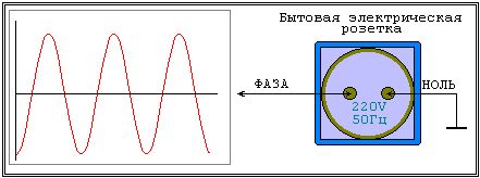
In this article we will talk about the parameters alternating current. For example, a familiar household outlet is a source of alternating current and alternating emf.
The change in EMF and the change in current of the linear load connected to such a source will occur according to a sinusoidal law. In this case, alternating EMF, alternating voltages and currents, can be characterized by their main four parameters:
period;
frequency;
amplitude;
effective value.
There are also auxiliary parameters:
angular frequency;
phase;
instantaneous value.
![]()
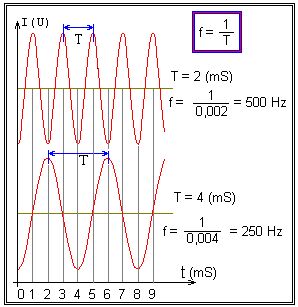
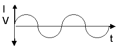
The period T of alternating current is the period of time during which the current or voltage makes one complete cycle of changes.
Since the source of alternating current is a generator, the period is related to the speed of rotation of its rotor, and the higher the speed of rotation of the coil or rotor of the generator, the smaller the period of the generated variable EMF, and, accordingly, the alternating current of the load.
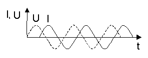
The period is measured in seconds, milliseconds, microseconds, nanoseconds, depending on the specific situation in which the current is considered. The above figure shows how the voltage U changes over time, while having a constant characteristic period T.
Frequency f is the reciprocal of the period, and is numerically equal to the number of periods of change in current or EMF in 1 second. That is, f = 1/T. The unit of frequency is the hertz (Hz), named after the German physicist Heinrich Hertz, who made significant contributions to the development of electrodynamics in the 19th century. The shorter the period, the higher the frequency of change of the emf or current.
Today in Russia the standard frequency of alternating current in electrical networks is 50 Hz, that is, 50 oscillations of the mains voltage occur in 1 second.
In other areas of electrodynamics, higher frequencies are used, for example 20 kHz and more - in modern inverters, and up to units of MHz in narrower areas of electrodynamics. The figure above shows that in one second there are 50 complete oscillations, each lasting 0.02 seconds, and 1/0.02 = 50.
From the graphs of changes in sinusoidal alternating current over time, it can be seen that currents of different frequencies contain different numbers of periods in the same period of time.
In one period, the phase of the sinusoidal EMF or sinusoidal current changes by 2pi radians or 360°, so the angular frequency of the alternating sinusoidal current is equal to:
![]()
The term “phase” refers to the stage of development of the process, and in in this case, in relation to alternating currents and sinusoidal voltages, the phase is the state of the alternating current at a certain point in time.
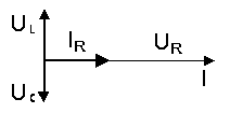
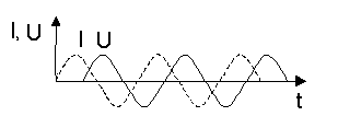
In the figures you can see: the coincidence of voltage U1 and current I1 in phase, voltages U1 and U2 in antiphase, as well as a phase shift between current I1 and voltage U2. The phase shift φ is measured in radians, fractions of a period, or degrees. Thus, the phase shift between current I1 and voltage U2 is equal to φ = π radians, as well as between voltage U1 and voltage U2.
Amplitude Um and Im
When talking about the magnitude of sinusoidal alternating current or sinusoidal alternating emf, highest value EMF or current is called amplitude or amplitude (maximum) value.
The greatest value of a quantity that performs harmonic oscillations (for example, the maximum value of current in an alternating current, the deviation of an oscillating pendulum from the equilibrium position), the greatest deviation of an oscillating quantity from a certain value, conventionally taken as the initial zero.
If we are talking about an alternating current generator, then the EMF at its terminals twice during a period reaches an amplitude value, the first of which is +Em, the second -Em, respectively, during the positive and negative half-cycles. The current I behaves in a similar way and is designated Im accordingly.
Instantaneous value of u and i
The value of emf or current at a specific this moment time is called the instantaneous value, they are denoted by small letters u and i. But since these values change all the time, it is inconvenient to judge alternating currents and EMF from them.
Effective values of I, E and U
The ability of alternating current to perform any useful work, for example, to mechanically rotate a motor rotor or produce heat on a heating device, it is convenient to evaluate the effective values of the emf and currents.
So, the meaning of this is called direct current, which, when passing through a conductor during one period of the alternating current in question, produces the same mechanical work or the same amount of heat as the given alternating current.
The effective values of voltages, emfs and currents are denoted by capital letters I, E and U. For sinusoidal alternating current and for sinusoidal alternating voltage, the effective values are:
The effective value of current and voltage is convenient to practically use to describe electrical networks. For example, a value of 220-240 volts is the effective voltage value in modern household sockets, and the amplitude is much higher - from 311 to 339 volts.
It’s the same with current, for example, when they say that a current of 8 amperes flows through a household heating device, this means the effective value, while the amplitude is 11.3 amperes.
Anyway, mechanical work and electrical energy in electrical installations are proportional to the effective values of voltages and currents. A significant part of the measuring instruments shows the actual values of voltages and currents.
Electricity- This is the directed or ordered movement of charged particles: electrons in metals, ions in electrolytes, and electrons and ions in gases. Electric current can be either direct or alternating.
Definition of direct electric current, its sources
D.C(DC, in English Direct Current) is an electric current whose properties and direction do not change over time. Direct current and voltage are indicated in the form of a short horizontal dash or two parallel ones, one of which is dashed.
Direct current is used in cars and in houses, in numerous electronic devices: laptops, computers, TVs, etc. The measured electric current from the outlet is converted into direct current using a power supply or voltage transformer with a rectifier.
Any power tool, device or device powered by batteries is also a consumer of direct current, because a battery or accumulator is exclusively a source of direct current, which, if necessary, is converted into alternating current using special converters (inverters).
Working principle of alternating current
Alternating current(AC in English Alternating Current) is an electric current that changes in magnitude and direction over time. On electrical appliances it is conventionally designated by a sine wave segment “~”.
Sometimes after the sinusoid the characteristics of alternating current may be indicated - frequency, voltage, number of phases.
Alternating current can be either single- or three-phase, for which the instantaneous values of current and voltage vary according to a harmonic law.
Main characteristics alternating current - effective voltage value and frequency.
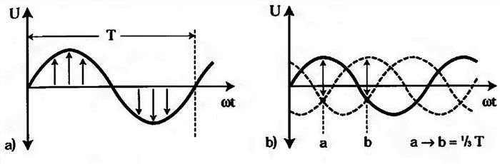
note, as on the left graph for a single-phase current the direction and magnitude of the voltage changes with a transition to zero over a period of time T, and on the second graph for a three-phase current there is a shift of three sinusoids by one third of the period. On the right graph, phase 1 is indicated by the letter “a”, and the second by the letter “b”. It is well known that the home socket has 220 volts. But few people know what it is valid value alternating voltage, but the amplitude or maximum value will be greater by the root of two, i.e. it will be equal to 311 Volts.
Thus, if for direct current the voltage magnitude and direction do not change over time, then for alternating current current-voltage constantly changing in magnitude and direction (the graph below zero is the opposite direction).
And so we came to the concept of frequency is the ratio of the number of complete cycles (periods) to a unit of time of periodically changing electric current. Measured in Hertz. Here and in Europe the frequency is 50 Hertz, in the USA it is 60 Hz.
What does a frequency of 50 Hertz mean? It means that our alternating current changes its direction to the opposite and back (segment T- on the graph) 50 times per second!
AC sources are all the outlets in the house and everything that is connected directly by wires or cables to the electrical panel. Many people have a question: why is there no direct current in the outlet? The answer is simple. In alternating current networks, the voltage is easily and with minimal losses converted to the required level using a transformer in any volume. The voltage must be increased to be able to transmit electricity over long distances with minimal losses in industrial scale. 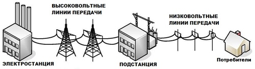 From the power plant, where powerful electric generators are located, a voltage of 330,000-220,000 comes out, then near our house at a transformer substation it is converted from a value of 10,000 Volts into a three-phase voltage of 380 Volts, which comes to apartment house, but single-phase voltage comes to our apartment, because the voltage between them is 220 V, and between opposite phases in the electrical panel it is 380 Volts.
And one more important advantage of alternating voltage is that asynchronous AC motors are structurally simpler and operate much more reliably than DC motors.
How to make alternating current constant
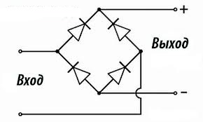
For consumers operating on direct current, alternating current is converted using rectifiers.
DC to AC converter
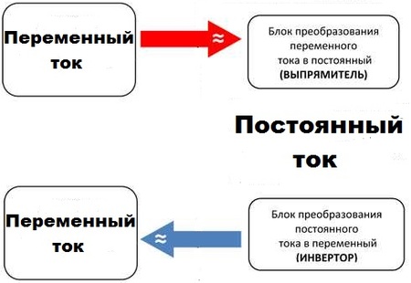 If there are no difficulties with converting alternating current to direct current, then with the reverse conversion everything is much more complicated. At home for this inverter is used- This is a generator of periodic voltage from a constant voltage, in shape close to a sinusoid.
Designations, parameters.
We know that a constant electric current is a current that does not change over time, both in magnitude and in the direction of movement of electrons. The main purpose of direct current is to power various radio and electronic equipment. Sources of direct current are batteries, solar photocells, batteries and direct current generators.
In everyday life and industry, alternating sinusoidal current is used. This is due to the fact that modern energy is based on the transfer of energy over long distances from hydro, thermal and nuclear power plants to the consumer. For getting electrical energy Power plants use alternating current generators. Transmission of alternating current is beneficial due to the advantages of its conversion and due to low losses in power lines. It is easy to convert alternating electric current into direct current, as well as obtain any desired alternating current voltage. For example, the alternating current voltage transmitted along power lines is several thousand volts. In residential areas, the power line is connected to a transformer that converts the high voltage to standard household voltage of 220 volts. It is this voltage that we have in the sockets of our apartments.
Standard frequency in household electrical network equal to 50 Hz. In some foreign countries the standard frequency is 60 Hz. Just like direct current, alternating current is transmitted through two wires. If direct current has two poles - plus and minus, then with alternating current one wire is current-carrying and is called “phase”, and the second wire is common and is called “ground” or “zero”. Household voltage electrical outlet equals 220 volts.
Unlike direct current, alternating sinusoidal current (as well as alternating voltage) changes over time in amplitude (magnitude) and direction of electron movement. On the graph, alternating current looks like a sinusoid.
The distance between two adjacent vertices on a graph of an alternating sinusoidal current is called a period and is denoted by the letter T. A period is the time of one oscillation of an alternating current. The period is measured in seconds or in smaller units of time: milliseconds; microseconds; nanoseconds, etc. Value: period T=1 sec. to the minus first power (T -1) or 1/T is called a frequency of 1 Hertz. Frequency is designated by the letter f. In radio and electronic devices, depending on their purpose, the frequency can be in units of hertz (Hz or Hz), thousands of hertz (kHz or kHz) and so on.
Unlike direct current, alternating electric current (or voltage) changes its value over time, from a maximum to a minimum value. In this regard, the value of alternating current or voltage will be slightly lower than the value of U or I. 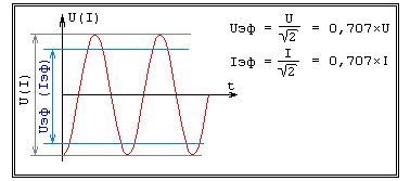
These values are called effective (rms) values of current or voltage and are designated Ieff and Ueff, respectively (see figure). These are the values shown by AC measuring instruments.
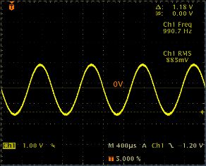
To study alternating current parameters, the most suitable measuring instrument is an oscilloscope. On the cathode ray tube of the oscilloscope - display (see figure) you can observe not only the shape of the alternating current, but also carry out a quantitative analysis of the signal under study. 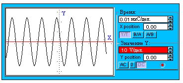
The X axis on the display is graduated in time divisions, and the Y axis is graduated in signal amplitude divisions. In the figure, the "Time" switch is set to a time of 0.01 microseconds per division along the X axis.
In the above figure, the signal period is equal to 2 divisions, therefore: T = 2 * 0.01 = 0.02 µS, and the signal frequency f = 1/T = 1/(0.02 -6) = 1/0.00000002 = 50000000 Hz = 50 MHz (MHz - megahertz ).
The Y Value switch is set to an amplitude of 10 volts per division along the Y axis. The signal has an amplitude of 6 divisions, therefore the signal voltage is 6 * 10 = 60 volts.
In conclusion of this topic, I would like to say that alternating sinusoidal current is used not only to power household and industrial electrical appliances. In radio and electronics, for example, high-frequency alternating current generators for radio transmitters are widely used (both high-power ones for television and radio studios, and low-power ones for cellular phones, pagers, etc.). In our subsequent topics, we will often encounter alternating electric current and the laws of its amplification, transformation, and so on.
Alternating current, in contrast to, continuously changes both in magnitude and direction, and these changes occur periodically, that is, they are repeated exactly at regular intervals.
To induce such a current in a circuit, they use alternating current sources that create an alternating emf that periodically changes in magnitude and direction. Such sources are called alternating current generators.
In Fig. Figure 1 shows a diagram of the device (model) of the simplest.
A rectangular frame made of copper wire is mounted on an axis and rotates in the field using a belt drive. The ends of the frame are soldered to copper contact rings, which, rotating with the frame, slide along the contact plates (brushes).
Figure 1. Diagram of a simple alternator
Let's make sure that such a device really is source of variable EMF.
Let us assume that a magnet creates between its poles, i.e., one in which the density of magnetic lines of force in any part of the field is the same. rotating, the frame crosses the lines of force magnetic field, and in each of its sides a and b.
Sides c and d of the frame are non-working, since when the frame rotates they do not intersect the magnetic field lines and, therefore, do not participate in the creation of the EMF.
At any moment of time, the EMF arising in side a is opposite in direction to the EMF arising in side b, but in the frame both EMFs act in accordance and in total constitute the total EMF, i.e., induced by the entire frame.
This is easy to verify if we use what we know to determine the direction of the EMF rule right hand .
To do this, you need to position the palm of your right hand so that it faces the north pole of the magnet, and the bent thumb coincides with the direction of movement of that side of the frame in which we want to determine the direction of the EMF. Then the direction of the EMF in it will be indicated by the outstretched fingers of the hand.
For whatever position of the frame we determine the direction of the EMF in sides a and b, they always add up and form a total EMF in the frame. In this case, with each revolution of the frame, the direction of the total EMF in it changes to the opposite, since each of the working sides of the frame passes under different poles of the magnet in one revolution.
The magnitude of the EMF induced in the frame also changes, as the speed at which the sides of the frame intersect the magnetic field lines changes. Indeed, at the time when the frame approaches its vertical position and passes it, the speed of intersection of the force lines by the sides of the frame is greatest, and the largest EMF is induced in the frame. At those moments in time when the frame passes its horizontal position, its sides seem to slide along the magnetic lines of force without crossing them, and no emf is induced.
Thus, with uniform rotation of the frame, an EMF will be induced in it, periodically changing both in magnitude and direction.
The EMF arising in the frame can be measured with a device and used to create a current in an external circuit.
Graphic representation of direct and alternating currents
The graphical method makes it possible to visually represent the process of changing a particular variable depending on time.
The construction of graphs of variables that change over time begins with the construction of two mutually perpendicular lines, called the axes of the graph. Then, segments of time are plotted on the horizontal axis on a certain scale, and on the vertical axis, also on a certain scale, the values of the quantity whose graph is going to be plotted (EMF, voltage or current).
In Fig. 2 are graphically depicted direct and alternating currents. In this case, we plot the current values, and vertically up from the point of intersection of the O axes we plot the current values of one direction, which is usually called positive, and down from this point - in the opposite direction, which is usually called negative.
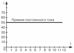
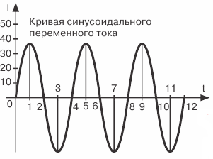
Figure 2. Graphical representation of DC and AC current
Point O itself serves simultaneously as the beginning of the countdown of current values (vertically down and up) and time (horizontally to the right). In other words, this point corresponds to the zero value of the current and the initial moment in time from which we intend to trace how the current will change in the future.
Let us verify the correctness of what is constructed in Fig. 2, and a graph of a constant current of 50 mA.
Since this current is constant, i.e., does not change its magnitude and direction over time, the same current values, i.e., 50 mA, will correspond to different moments in time. Therefore, at a time equal to zero, i.e. at the initial moment of our observation of the current, it will be equal to 50 mA. By plotting upward on the vertical axis a segment equal to the current value of 50 mA, we get the first point of our graph.
We must do the same for the next moment in time, corresponding to point 1 on the time axis, i.e., set aside a segment vertically upward from this point, also equal to 50 mA. The end of the segment will determine the second point of the graph.
Having carried out a similar construction for several subsequent moments in time, we will obtain a series of points, the connection of which will give a straight line, which is graphical representation of DC current value 50 mA.
Let's now move on to studying variable emf graph. In Fig. 3 at the top shows a frame rotating in a magnetic field, and at the bottom is a graphical representation of the emerging EMF variable.
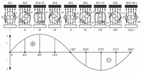
Figure 3. Plotting a graph of the variable EMF
Let's begin to uniformly rotate the frame clockwise and follow the progress of the change in the EMF in it, taking the horizontal position of the frame as the initial moment.
At this initial moment, the EMF will be zero, since the sides of the frame do not intersect the magnetic lines of force. On the graph, this zero EMF value corresponding to the moment t = 0 will be represented by point 1.
With further rotation of the frame, an emf will begin to appear in it and will increase in magnitude until the frame reaches its vertical position. On the graph, this increase in EMF will be depicted as a smooth upward curve that reaches its peak (point 2).
As the frame approaches the horizontal position, the emf in it will decrease and drop to zero. On the graph this will be depicted as a descending smooth curve.
Consequently, during the time corresponding to half a revolution of the frame, the EMF in it managed to increase from zero to its maximum value and again decrease to zero (point 3).
With further rotation of the frame, an emf will again arise in it and will gradually increase in value, but its direction will already change to the opposite, which can be verified by applying the right-hand rule.
The graph takes into account the change in the direction of the EMF in that the curve depicting the EMF intersects the time axis and is now located below this axis. The EMF increases again until the frame takes a vertical position.
Then the EMF will begin to decrease, and its value will become zero when the frame returns to its original position, having completed one full revolution. On the graph this will be expressed by the fact that the EMF curve, having reached its peak in the opposite direction (point 4), then meets the time axis (point 5)
This ends one cycle of changing the EMF, but if we continue to rotate the frame, a second cycle immediately begins, exactly repeating the first, which, in turn, will be followed by a third, and then a fourth, and so on until we stop the rotation framework.
Thus, for each revolution of the frame, the EMF arising in it completes a full cycle of its change.
If the frame is closed to any external circuit, then an alternating current will flow through the circuit, the graph of which will be the same in appearance as the EMF graph.
The wave-like curve we obtained is called a sine wave, and the current, emf or voltage changing according to this law is called sinusoidal.
The curve itself is called a sine wave because it is a graphical representation of a variable trigonometric quantity called sine.
The sinusoidal nature of current change is the most common in electrical engineering, therefore, when speaking about alternating current, in most cases we mean sinusoidal current.
To compare different alternating currents (EMF and voltages), there are quantities that characterize a particular current. They're called AC parameters.
Period, amplitude and frequency - parameters of alternating current
Alternating current is characterized by two parameters - period and amplitude, knowing which we can judge what kind of alternating current it is and build a current graph.
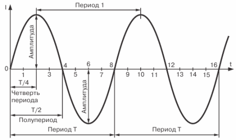
Figure 4. Sinusoidal current curve
The period of time during which a complete cycle of current change occurs is called a period.
The period is designated by the letter T and is measured in seconds.The period of time during which half of the complete cycle of current change occurs is called a half-cycle. Consequently, the period of change of current (EMF or voltage) consists of two half-cycles. It is quite obvious that all periods of the same alternating current are equal to each other.
As can be seen from the graph, during one period of its change the current reaches twice its maximum value.
The maximum value of an alternating current (emf or voltage) is called its amplitude or amplitude current value.
Im, Em and Um are generally accepted designations for the amplitudes of current, EMF and voltage.
We first of all paid attention to , however, as can be seen from the graph, there are countless intermediate values that are smaller than the amplitude.
The value of alternating current (EMF, voltage) corresponding to any selected moment in time is called its instantaneous value.
i, e and u are generally accepted designations for instantaneous values of current, emf and voltage.
The instantaneous current value, as well as its amplitude value, can be easily determined using a graph. To do this, from any point on the horizontal axis corresponding to the moment of time we are interested in, we draw a vertical line to the point of intersection with the current curve; the resulting segment of the vertical straight line will determine the value of the current in this moment, i.e. its instantaneous value.
It is obvious that the instantaneous value of the current after time T/2 from the starting point of the graph will be equal to zero, and after time T/4 its amplitude value. The current also reaches its amplitude value; but in the opposite direction, after a time equal to 3/4 T.
So, the graph shows how the current in the circuit changes over time, and that each moment in time corresponds to only one specific value of both the magnitude and direction of the current. In this case, the value of the current at a given moment in time at one point in the circuit will be exactly the same at any other point in this circuit.
The number of complete periods completed by a current in 1 second is called AC frequency and is denoted by the Latin letter f.
To determine the frequency of alternating current, i.e. find out how many periods of change does the current complete within 1 second?, it is necessary to divide 1 second by the time of one period f = 1/T. Knowing the frequency of the alternating current, you can determine the period: T = 1/f
It is measured in a unit called the hertz.
If we have alternating current, the frequency of which is equal to 1 hertz, then the period of such current will be equal to 1 second. And, conversely, if the period of current change is 1 second, then the frequency of such current is 1 hertz.
So we have defined AC parameters - period, amplitude and frequency, - which make it possible to distinguish different alternating currents, emfs and voltages from each other and to construct their graphs when necessary.
When determining the resistance of various circuits to alternating current, use another auxiliary quantity characterizing alternating current, the so-called angular or circular frequency.
Circular frequency denoted by the letter ω and is related to the frequency f by the relation ω = 2π f
Let us explain this dependence. When constructing a graph of the variable EMF, we saw that during one full revolution of the frame, a complete cycle of change in the EMF occurs. In other words, in order for the frame to make one revolution, i.e., turn 360°, it takes time equal to one period, i.e. T seconds. Then in 1 second the frame makes a 360°/T revolution. Therefore, 360°/T is the angle through which the frame rotates in 1 second, and expresses the speed of rotation of the frame, which is commonly called angular or circular speed.
But since the period T is related to the frequency f by the ratio f = 1/T, the circular speed can be expressed in terms of frequency and will be equal to ω = 360°f.
So, we came to the conclusion that ω = 360°f. However, for the convenience of using the circular frequency in all kinds of calculations, the angle of 360° corresponding to one revolution is replaced by a radial expression equal to 2π radians, where π = 3.14. Thus, we finally obtain ω = 2π f. Therefore, to determine the circular frequency of alternating current (), the frequency in hertz must be multiplied by a constant number 6.28.
Electricity
Variable and its use in medicine.
- Alternating current, its types and main characteristics.
Alternating current is a current whose direction and numerical value changes over time (alternating current).
Note: the shape of the current curve, frequency, and duration of its change are not specified.
In practice, alternating current most often means periodic alternating current.
The physical essence of alternating current boils down to oscillations of electrical charges in a medium (conductor or dielectric).
Types of current:
Conduction current.
Bias current.
Conduction current- this is a current that is caused by vibrations of electrons and ions in the medium.
Bias current– this is a current that is caused by the displacement of electric charges at the “conductor-dielectric” boundary (for example, current through a capacitor).
The displacement current is associated with the change in time of the electric field at the conductor-dielectric interface and has the following features:
The amplitude of the displacement current and its direction are in phase with those of the conduction current.
Its value is always equal to the conduction current.
A special case of displacement current is polarization current. Polarization current is a displacement current not in a vacuum, but in a material dielectric medium.
The sum of the displacement and polarization currents is total bias current.
In medical practice, the following types of currents are used according to the shape of the current curve:
Needle-exponential
The simplest is the periodic sinusoidal current. It is easily described mathematically and graphically; its shape is not distorted in electrical circuits with R, C, L elements.
Basic characteristics of alternating current.
Period– time of one cycle of current change in direction and numerical value (T, s).
Frequency is the number of cycles of current change per unit time.
=1/T (the reciprocal of the period s -1, Hz)
Circular frequency( , 2 /T radian/s)
Phase() is a quantity that determines the relationship of current and voltage in an electrical circuit over time.
Instantaneous current and voltage- the value of these quantities at a given time (i, u).
Amplitude value of current and voltage– this is the maximum value of these quantities (I m, U m) during the half-cycle.
RMS (rms, effective) value of current and voltage- is calculated as the positive square root of the average value of the square of voltage or current using the formulas.
I = I 2 cp
U = U 2 cp
Average value (U Wed ) for the period (constant component) is the arithmetic average of instantaneous current or voltage values over a period.
In practice, the root mean square value is determined by the effective (rms) value. (I cp, U cp), which for sinusoidal current is calculated using the formulas:
Ieff = I = 0.707 I m
Ueff = U = 0.707 Um
In some cases of medical use of electric current, it is necessary to take into account other characteristics (for example, the amplitude coefficient K a, and the shape coefficient K f).
The following formulas for connecting characteristics are important for practice:
i(u) ≤I m (U m)
I eff = I = I m / 2 =0.707 I m I m = 1.41 I eff
U eff = U= U m / 2 =0.707 U m U m = 1.41 U eff
2. AC circuits with active resistance, inductance, capacitance and their features.
Electrical circuit- this is a real or conceivable set of physical elements that transmit electrical energy from one point in space to another.
The physical elements of electrical circuits are conductors, resistors, capacitors, and inductors. The elements of a circuit are also elements of its connection, and, in addition, they implement the corresponding properties of resistance, capacitance and inductance.
Types of electrical circuits:
Simple chains contain only single R, C, L elements, while complex chains have them in various quantities and combinations.
A common feature of the elements of an electrical circuit is that when alternating current passes, they exhibit resistance, which is called active (R), inductive (X l), capacitive (X c).
Features of simple ideal chains.
A circuit consisting of a current generator and an ideal resistor is called a simple circuit with active resistance.
Condition for ideality of the chain:
Active resistance is not zero,
its inductance and capacitance are zero.
R 0
C  r = 0 ~ R
Peculiarities:
There is no phase shift () between current and voltage.
This means that current and voltage simultaneously pass through their maximum (amplitude) and zero values.
At the R-element, energy loss occurs in the form of heat release.
Circuit with inductance- this is an electrical circuit consisting of an alternating current generator and an ideal L - element - an inductor.
U 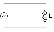 chain ideality conditions:
Coil inductance is not zero
Its capacitance and resistance are zero.
L 0
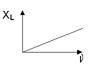
Chain Features:
X L = L = 2 L
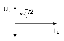
There is a phase shift in the circuit between voltage and current: V is ahead of I in phase by an angle /2
Inductive reactance does not consume energy because
 it is stored in the magnetic field of the coil and then released into the electrical circuit. Therefore, inductive reactance is called apparent or imaginary. Chain with container
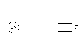
is an electrical circuit consisting of an alternating current generator and an ideal C-element - a capacitor.
Conditions for an ideal chain:
The capacitance of the capacitor is not zero, but its active resistance and inductance are zero. C 0, R C = 0, L C = 0.
1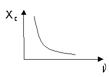 Features of the chain with capacitance:
. Ohm's law is observed.
2. The capacitance provides alternating current resistance, which is called capacitive. It is denoted by X s and does not decrease linearly with increasing frequency.
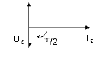
There is a phase shift in the circuit between voltage and current: V lags behind I in phase by an angle /2
- Capacitance does not consume energy, because
it is stored in the electric field of the capacitor and then released into the electrical circuit. Therefore, capacitance is called apparent or imaginary.
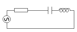
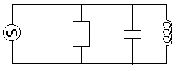
To analyze the processes taking place in electrical circuits, complete serial and parallel circuits are used.
A series circuit is a circuit where all the elements can be connected in series, one after the other.
In a parallel circuit, R, C, L elements are connected in parallel.
Full Circuit Features:
Ohm's law is observed
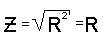
The complete circuit provides resistance to alternating current.
This resistance is called total (imaginary, apparent) or impedance.
![]()
Impedance depends on the resistance of all elements of the circuit, is denoted by Z and is calculated not by simple, but by geometric (vector) summation.
For series-connected elements, the impedance formula has the following meaning:
Z is the impedance of the series circuit,
R - active resistance,
X L – inductive and X C – capacitive reactance,
L - coil inductance (Henry),
C is the capacitance of the capacitor (farad).
- Since capacitive and inductive reactances give the voltage a phase shift in the opposite direction, it is possible that X L = X C . In this case, the algebraic sum of the modules will be equal to zero, and the impedance will be the smallest.
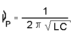
The condition in which the capacitive reactance in an alternating current circuit is equal to the inductive reactance is called voltage resonance. The frequency at which X L = X C is called the resonant frequency. This frequency p can be determined using Thomson’s formula:
Features of living tissue impedance and its equivalent electrical circuit.
When current is passed through living tissue, it can be considered as an electrical circuit consisting of certain elements.
It has been experimentally established that this circuit has the properties of active resistance and capacitance. This is evidenced by the release of heat and the decrease in tissue impedance with increasing frequency. The inductive properties of living tissue are practically undetectable. Thus, living tissue is a complex, but not complete, electrical circuit.
The impedance of living tissue can be considered for both series and parallel connection of its elements.
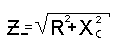
In a series connection, the currents through the elements are equal, the total applied voltage will be the vector sum of the voltages on the R and C elements, and the series circuit impedance formula will be:
Z_ is the impedance of the series circuit,
R is its active resistance,
Theoretical formulas for the impedance of living tissue with parallel and series connection of its elements differ from experimental ones in the following:
With a series connection circuit, practical data give large deviations at low frequencies.
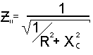
In a parallel circuit, these measurements show a final Z value, although theoretically it should tend to zero.
Equivalent electrical circuit of living tissue - e This is a conditional model that approximately characterizes living tissue as an alternating current conductor.
The diagram allows us to judge:
What electrical elements does fabric have?
How are these elements connected?
How the properties of the tissue will change when the frequency of the current changes.
The scheme is based on three provisions:
The extracellular environment and the contents of the cell are ionic conductors with an active resistance of the environment Rav and the cell Rk.
The cell membrane is a dielectric, but not ideal, but with low ionic conductivity, and, consequently, membrane resistance Rm.
The extracellular environment and the contents of the cell, separated by a membrane, are capacitors Cm of a certain capacity (0.1 - 3.0 μF / cm 2).
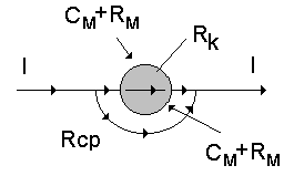
If we take a liquid tissue medium—blood, containing only red blood cells—as a model of living tissue, then when drawing up an equivalent circuit, we must take into account the paths of the electric current.
Bypassing the cell, through the extracellular environment.
Through the cage.
The path around the cell is represented only by the resistance of the medium Rav.
The path through the cell is by the resistance of the cell contents Rk, as well as by the resistance and capacitance of the membrane. Rm, See.
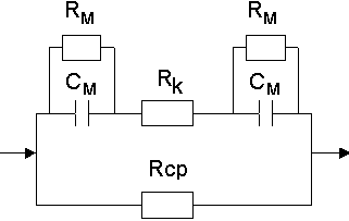
If we replace the electrical characteristics with the appropriate designations, we obtain equivalent circuits of varying degrees of accuracy:
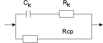
Fricke scheme (ionic conductivity not
taken into account).
Schwan scheme (ionic conductivity is taken into account as membrane resistance)
Symbols on the diagram:
Rcp - active resistance of the cellular environment
Rk - Resistance of cellular contents
Cm - membrane capacity
Rm - membrane resistance.
Analysis of the circuit shows that with increasing current frequency, the conductivity of cell membranes increases, and impedance tissue environment decreases, which corresponds to practically carried out measurements.
5. Living tissue as a conductor of alternating electric current. Dispersion of electrical conductivity and its quantitative assessment.
The following features of living tissue as a conductor of alternating current have been experimentally established:
1. The resistance of living tissue to alternating current is less than to direct current.
2. The electrical characteristics of the fabric depend both on its type and on the frequency of the current.
3. With increasing frequency, the total resistance of living tissue decreases nonlinearly to a certain value, and then remains almost constant (mostly at frequencies above 10 6 Hz)
4. At a certain frequency, the impedance also depends on the physiological state (blood supply), which is used in practice.
The study of peripheral circulation based on the measurement of electrical resistance is called rheography (impedance plethysmography).
5. When living tissue dies, its resistance decreases and does not depend on frequency.
6. When alternating current passes through living tissue, a phenomenon called electrical conductivity dispersion is observed. 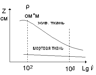 D
D
Electrical conductivity dispersion is the phenomenon of the dependence of the total (specific) resistance of living tissue on the frequency of alternating current.
Graphs of such dependence are called dispersion curves. Dispersion curves are plotted in a rectangular coordinate system, where the values of total (Z) or resistivity are plotted vertically, and the frequency on a logarithmic scale (Lg ) is plotted horizontally.
The frequency dependences of the curve shape for different tissues are similar, but differ in the resistance value.
There are several frequency ranges where dispersion is particularly pronounced.
One of them corresponds to the interval 10 2 -10 6 Hz
Dispersion Features:
1. Inherent only in living tissues.
2. More pronounced at frequencies up to 1 MHz.
3. In practice, it is used to assess the physiological state and viability of tissues.
Quantitative assessment of dispersion is carried out using the dispersion coefficient (K).
The dispersion coefficient is a dimensionless quantity equal to the ratio of low-frequency (10 2) impedance (or specific) to high-frequency (10 6 Hz).
Z 1 – impedance at frequency 10 2 Hz
Z 2 – impedance at frequency 10 6 Hz
The phenomenon of dispersion is associated with the presence of polarization in living tissues, which has less effect on the total resistance with increasing frequency.
Therefore, the dispersion coefficient is often called the polarization coefficient.
In addition to frequency dependencies, living tissues exhibit phase shifts between current and voltage, which also, but to a lesser extent, depend on frequency.
Phase shifts also decrease as tissues die and, in the future, can be used for practical purposes.
Similar abstracts: The procedure for determining the degree of conductivity electrical circuit
according to Kirchhoff's law. Effective voltage complex. Vector diagram of this circuit. Active, reactive and admittance circuits. The essence of Kirchhoff's laws for sinusoidal current circuits.
Study of processes in a single-phase electrical circuit with parallel connection of receivers containing inductive and capacitive elements, with different ratios of their parameters. Experimental determination of the conditions for achieving current resonance in a given circuit.
Calculation of a branched DC circuit with one or more energy sources and a branched sinusoidal alternating current circuit. Construction of a vector diagram based on the values of currents and voltages. Calculation of a three-phase alternating current circuit.
Forced oscillations are those oscillations that are caused by the action of external forces on a system that periodically change over time. In the case of electromagnetic oscillations, such an external force is a periodically changing emf. current source. The influence of the coil inductance on electrical parameters