DIY electronic table clock. DIY LED clock. Description of the clock
Hello geektimes! The first part of the article discussed the principles of obtaining accurate time on a homemade watch. Let's go further and consider how and on what it is better to display this time.
1. Output devices
So, we have a certain platform (Arduino, Raspberry, PIC/AVR/STM controller, etc), and the task is to connect some kind of indication to it. There are many options that we will consider.Segment display
Everything is simple here. The segment indicator consists of ordinary LEDs, which are simply connected to the microcontroller through quenching resistors.Beware of traffic!
Pros: simplicity of design, good viewing angles, low price.
Cons: The amount of information displayed is limited.
There are two types of indicator designs, with a common cathode and a common anode; inside it looks something like this (diagram from the manufacturer’s website). 
There are 1001 articles on how to connect an LED to a microcontroller, Google can help. Difficulties begin when we want to make a large clock - after all, looking at a small indicator is not particularly convenient. Then we need the following indicators (photo from eBay): 
They are powered by 12V, and they simply won’t work directly from the microcontroller. This is where the microcircuit comes to our aid. CD4511, just for this purpose. It not only converts data from a 4-bit line into the desired numbers, but also contains a built-in transistor switch to supply voltage to the indicator. Thus, in the circuit we will need to have a “power” voltage of 9-12V, and a separate step-down converter (for example L7805) to power the “logic” of the circuit.
Matrix indicators
Essentially, these are the same LEDs, only in the form of an 8x8 matrix. Photo from eBay:
They are sold on eBay in the form of single modules or ready-made blocks, for example 4 pieces. Managing them is very simple - a microcircuit is already soldered onto the modules MAX7219, ensuring their operation and connection to the microcontroller using only 5 wires. There are many libraries for Arduino, anyone can look at the code.
Pros: low price, good viewing angles and brightness.
Cons: low resolution. But for the inference task, the time is quite enough.
LCD indicators
LCD indicators can be graphic or text.
Graphic ones are more expensive, but they allow you to display more varied information (for example, a graph of atmospheric pressure). Text ones are cheaper and easier to work with, they also allow you to display pseudo-graphics - it is possible to load custom symbols into the display.
Working with an LCD indicator from code is not difficult, but there is a certain disadvantage - the indicator requires many control lines (from 7 to 12) from the microcontroller, which is inconvenient. Therefore, the Chinese came up with the idea of combining an LCD indicator with an i2c controller, which ended up being very convenient - only 4 wires are enough to connect (photo from eBay). 
LCD indicators are quite cheap (if you buy them on eBay), large, easy to connect, and can display a variety of information. The only negative is that the viewing angles are not very large.
OLED indicators
They are an improved continuation of the previous version. They range from small and cheap with a diagonal of 1.1", to large and expensive. Photo from eBay.
Actually, they are good in everything except the price. As for small indicators, 0.9-1.1" in size, then (except for learning how to work with i2c) it is difficult to find any practical use for them.
Gas discharge indicators (IN-14, IN-18)
These indicators are now very popular, apparently due to the “warm tube sound of light” and the originality of the design.
(photo from nocrotec.com)
Their connection diagram is somewhat more complicated, because These indicators use a voltage of 170V for ignition. A converter from 12V=>180V can be made on a microcircuit MAX771. A Soviet microcircuit is used to supply voltage to the indicators K155ID1, which was created specifically for this purpose. The issue price for self-production: about 500 rubles for each indicator and 100 rubles for K155ID1, all other parts, as they wrote in old magazines, “are not in short supply.” The main difficulty here is that both IN-xx and K155ID1 have long been out of production, and you can only buy them at radio markets or in a few specialized stores.
2. Platform selection
We have more or less figured out the display, all that remains is to decide which hardware platform is best to use. There are several options here (I’m not considering homemade ones, because those who know how to route a board and solder a processor don’t need this article).Arduino
The easiest option for beginners. The finished board is inexpensive (about $10 on eBay with free shipping) and has all the necessary connectors for programming. Photo from eBay:
There are a huge number of different libraries for Arduino (for example, for the same LCD screens, real-time modules), Arduino is hardware compatible with various additional modules.
The main disadvantage: the complexity of debugging (only through the serial port console) and a rather weak processor by modern standards (2KB RAM and 16MHz).
The main advantage: you can do a lot of things, practically without bothering with soldering, buying a programmer and wiring boards; you just need to connect the modules to each other.
32-bit STM processors
For those who want something more powerful, there are ready-made boards with STM processors, for example a board with STM32F103RBT6 and a TFT screen. Photo from eBay:
Here we already have full-fledged debugging in a full-fledged IDE (out of all the different ones, I liked the Coocox IDE best), however, we will need a separate ST-LINK programmer-debugger with a JTAG connector (the issue price is $20-40 on eBay). Alternatively, you can buy the STM32F4Discovery development board, on which this programmer is already built-in, and it can be used separately.
Raspberry PI
And finally, for those who want full integration with the modern world, there are single-board computers with Linux, probably already known to everyone - Raspberry PI. Photo from eBay:
This is a full-fledged computer with Linux, a gigabyte of RAM and a 4-core processor on board. A panel of 40 pins is located on the edge of the board, allowing you to connect various peripherals (pins are available from code, for example in Python, not to mention C/C++), there is also a standard USB in the form of 4 connectors (you can connect WiFi). There is also standard HDMI.
The board’s power is enough, for example, not only to display the time, but also to run an HTTP server for setting parameters via a web interface, loading a weather forecast via the Internet, and so on. In general, there is a lot of room for flight of fancy.
There is only one difficulty with Raspberry (and STM32 processors) - its pins use 3-V logic, and most external devices (for example LCD screens) operate the “old-fashioned” way from 5V. Of course, you can connect it this way, and in principle it will work, but this is not quite the correct method, and it’s kind of a shame to ruin a $50 board. The correct way is to use a “logic level converter”, which costs only $1-2 on eBay.
Photo from eBay: 
Now it is enough to connect our device through such a module, and all parameters will be consistent.
ESP8266
The method is rather exotic, but quite promising due to the compactness and low cost of the solution. For very little money (about $4-5 on eBay) you can buy an ESP8266 module containing a processor and WiFi on board.Photo from eBay:

Initially, such modules were intended as a WiFi bridge for exchange via a serial port, but enthusiasts have written many alternative firmware that allow them to work with sensors, i2c devices, PWM, etc. Hypothetically, it is quite possible to receive time from an NTP server and output it via i2c to the display. For those who want to connect a lot of different peripherals, there are special NodeMCU boards with a large number of pins, the price is about 500 rubles (of course on eBay): 
The only negative is that the ESP8266 has very little RAM (depending on the firmware, from 1 to 32 KB), but this makes the task even more interesting. The ESP8266 modules use 3V logic, so the level converter above will also come in handy here.
This concludes the introductory excursion into homemade electronics; the author wishes everyone successful experiments.
Instead of a conclusion
I eventually settled on using a Raspberry PI with a text indicator configured to work with pseudo-graphics (which turned out to be cheaper than a graphic screen of the same diagonal). I took a photo of the desktop clock screen while writing this article.
The clock displays the exact time taken from the Internet, and the weather is updated from Yandex, all this is written in Python, and has been working quite well for several months now. At the same time, an FTP server is running on the watch, which allows (coupled with port forwarding on the router) to update its firmware not only from home, but also from any place where there is Internet. As a bonus, Raspberry resources, in principle, are enough to connect a camera and/or microphone with the ability to remotely monitor the apartment, or to control various modules/relays/sensors. You can add all sorts of “goodies”, such as LED indication of incoming mail, and so on.
PS: Why eBay?
As you can see, prices or photos from eBay were given for all devices. Why is that? Unfortunately, our stores often live by the principle “bought for $1, sold for $3, and live on that 2 percent.” As a simple example, Arduino Uno R3 costs (at the time of writing) 3600 rubles in St. Petersburg, and 350 rubles on eBay with free shipping from China. The difference is truly an order of magnitude, without any literary exaggeration. Yes, you will have to wait a month to pick up the parcel at the post office, but I think such a difference in price is worth it. But however, if someone needs it right now and urgently, then there is probably a choice in local stores, here everyone decides for themselves.
On sale you can find many different models and options of electronic digital watches, but most of them are designed for indoor use, since the numbers are small. However, sometimes it is necessary to place a clock on the street - for example, on the wall of a house, or in a stadium, square, that is, where it will be visible from a great distance by many people. For this purpose, this circuit of a large LED clock was developed and successfully assembled, to which you can connect (via internal transistor switches) LED indicators of any size. You can enlarge the schematic diagram by clicking on it:

Description of the clock
- Watch. In this mode there is a standard type of time display. There is a digital correction of the clock accuracy.
- Thermometer. In this case, the device measures the temperature of the room or air outside from one sensor. Range from -55 to +125 degrees.
- Power supply control is provided.
- Displays information on the indicator alternately - a clock and a thermometer.
- To save settings and settings when 220V is lost, non-volatile memory is used.

The basis of the device is the ATMega8 MK, which is flashed by setting fuses according to the table:

Operation and clock management
When you turn on the watch for the first time, an advertising splash screen will appear on the screen, after which it will switch to displaying the time. Pressing a button SET_TIME the indicator will go in a circle from the main mode:
- minutes and seconds display mode. If in this mode you simultaneously press the button PLUS And MINUS, then the seconds will be reset;
- setting the minutes of the current time;
- setting the current time clock;
- symbol t. Setting the duration of the clock display;
- symbol o. Display time of external temperature indication symbols (out);
- the amount of daily correction of the clock accuracy. Symbol c and correction value. Setting limits from -25 to 25 sec. The selected value will be added or subtracted from the current time every day at 0 hours 0 minutes and 30 seconds. For more details, read the instructions that are in the archive with the firmware and printed circuit board files.

Setting the clock
While holding down the buttons PLUS/MINUS We do accelerated setting of values. After changing any settings, after 10 seconds the new values will be written to non-volatile memory and will be read from there when the power is turned on again. New settings take effect during installation. The microcontroller monitors the presence of main power. When it is turned off, the device is powered from an internal source. The redundant power module diagram is shown below:

To reduce current consumption, the indicator, sensors and buttons are turned off, but the clock itself continues to count time. As soon as the 220V mains voltage appears, all indication functions are restored.

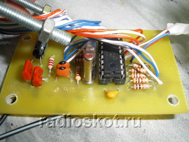
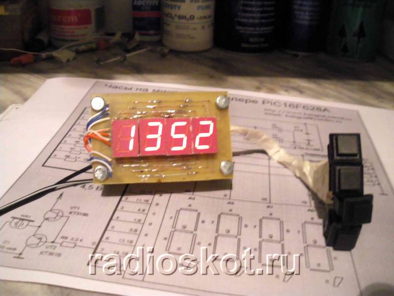
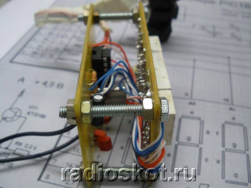
Since the device was conceived as a large LED clock, it has two displays: a large LED - for the street, and a small LCD - for easy setup of the main display. The large display is located several meters from the control unit and is connected by two cables of 8 wires. To control the anodes of the external indicator indicator, transistor switches are used according to the diagram given in the archive. Project authors: Alexandrovich & SOIR. I propose for repetition the circuit of a simple electronic clock with an alarm clock, made on the PIC16F628A type. A big advantage of this watch is the ALS type LED indicator for displaying the time. Personally, I’m pretty tired of all kinds of LCDs and I want to be able to see the time from anywhere in the room, including in the dark, and not just directly with good lighting. The circuit contains a minimum of parts and has excellent repeatability. The watch was tested for a month, which showed its reliability and performance. I think of all the schemes on the Internet, this one is the easiest to assemble and run.
Schematic diagram of an electronic clock with an alarm clock on a microcontroller:
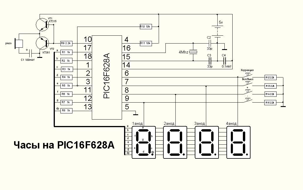
As can be seen from the clock diagram, it is the only microcircuit used in this device. A 4 MHz quartz resonator is used to set the clock frequency. To display the time, red indicators with a common anode are used; each indicator consists of two digits with decimal points. In the case of using a piezo emitter, capacitor C1 - 100 μF can be omitted.
You can use any indicators with a common anode, as long as each digit has its own anode. To ensure that the electronic watch is clearly visible in the dark and from a great distance, try to choose a larger ALS.

The clock display is dynamic. At a given time, only one digit is displayed, which allows you to significantly reduce current consumption. The anodes of each digit are controlled by a PIC16F628A microcontroller. The segments of all four digits are connected together and, through current-limiting resistors R1 ... R8, connected to the terminals of the MK port. Since the indicator lights up very quickly, the flickering of the numbers becomes unnoticeable.
Momentary buttons are used to set minutes, hours and alarm clock. Pin 10 is used as an output for the alarm signal, and a cascade of transistors VT1,2 is used as an amplifier. The sound emitter is a piezoelectric element of the ZP type. To improve the volume, you can replace it with a small speaker.
The clock is powered from a stabilized 5V source. It can also be powered by batteries. The watch has 9 display modes. Switching between modes is carried out using the “+” and “-” buttons. Before the readings themselves are displayed, a short hint about the name of the mode is displayed on the indicators. The duration of the hint display is one second.

Using the "Correction" button, the alarm clock is switched to settings mode. In this case, a short-term prompt is displayed for half a second, after which the adjusted value begins to blink. Correction of readings is carried out using the “+” and “-” buttons. When you press the button for a long time, the auto-repeat mode is activated at the specified frequency. All values, except hours, minutes and seconds, are written to EEPROM and restored after power cycle.

If no button is pressed within a few seconds, the electronic clock switches to time display mode. By pressing the "On/Off" button the alarm clock turns on or off, this action is confirmed by a short sound. When the alarm clock is on, the dot in the low-order digit of the indicator lights up. I was thinking about where to put the clock in the kitchen, and decided to mount it directly into the gas stove :) The material was sent by in_sane.
Discuss the article ELECTRONIC ALARM CLOCK
Not long ago there became a need to have a clock in the house, but only an electronic one, since I don’t like clocks, because they tick. I have quite a bit of experience in soldering and etching circuits. After scouring the Internet and reading some literature, I decided to choose the simplest scheme, since I don’t need a watch with an alarm clock.
I chose this scheme because it’s easy make your own watch
Let's get started, so what do we need in order to make a watch with our own hands? Well, of course, hands, skill (not even great) in reading circuit diagrams, soldering iron and parts. Here's a complete list of what I used:
10 MHz quartz – 1 pc., ATtiny 2313 microcontroller, 100 Ohm resistors – 8 pcs., 3 pcs. 10 kOhm, 2 capacitors of 22 pF, 4 transistors, 2 buttons, LED indicator 4-bit KEM-5641-ASR (RL-F5610SBAW/D15). I performed the installation on a one-sided PCB.
But there is a flaw in this scheme: the pins of the microcontroller (hereinafter referred to as MK), which are responsible for controlling the discharges, receive quite a decent load. The total current is much higher than the maximum port current, but with dynamic indication the MK does not have time to overheat. To prevent the MK from malfunctioning, we add 100 Ohm resistors to the discharge circuits.
In this scheme, the indicator is controlled according to the principle of dynamic indication, according to which the indicator segments are controlled by signals from the corresponding outputs of the MK. The repetition rate of these signals is more than 25 Hz and because of this, the glow of the indicator numbers seems continuous.
Electronic watches made according to the above scheme can only show time (hours and minutes), and seconds are shown by a dot between the segments, which is flashing. To control the operating mode of the watch, push-button switches are provided in its structure, which control the setting of hours and minutes. This circuit is powered from a 5V power supply. During the manufacture of the printed circuit board, a 5V zener diode was included in the circuit.

Since I have a 5V power supply, I excluded the zener diode from the circuit.
To make the board, the circuit was applied using an iron. That is, the printed circuit was printed on an inkjet printer using glossy paper; it can be taken from modern glossy magazines. Afterwards, the textolite of the required size was cut out. My size turned out to be 36*26 mm. Such a small size is due to the fact that all parts are selected in an SMD package.
The board was etched using ferric chloride (FeCl 3 ). The etching took about an hour, since the bath with the board was on the fireplace; high temperature affects the etching time; no copper was used in the board. But don't overdo it with the temperature.
While the etching process was going on, so as not to rack my brains and write firmware for the clock to work, I went to the Internet and found firmware for this scheme. How to flash MK can also be found on the Internet. I used a programmer that flashes only ATMEGA MKs.
And finally, our board is ready and we can start soldering our watches. For soldering, you need a 25 W soldering iron with a thin tip so as not to burn the MK and other parts. We carry out soldering carefully and preferably solder all the legs of the MK the first time, but only separately. For those who are not in the know, know that parts made in an SMD package have tin on their terminals for quick soldering.
And this is what the board looks like with soldered parts.

Homemade wristwatch with a vacuum indicator, made in steampunk style. Material taken from www.johngineer.com. This wristwatch is assembled on the basis of the IVL-2 display. I originally bought several of these indicators to create a standard table clock, but after some thought I realized that I could build a stylish wristwatch too. The indicator has a number of features that make it more suitable for this purpose than most other Soviet displays. Here are the parameters:
- The rated filament current is 60mA 2.4V, but works with 35mA 1.2V.
- Small size - only 1.25 x 2.25"
- Can work with relatively low grid voltage 12V (up to 24)
- Consumes only 2.5 mA/segment at 12.5V
All photos can be made larger by clicking on them. The biggest obstacle to the successful completion of the project was food. Since this watch was intended to be part of a costume, it doesn’t matter that the battery only lasts 10 hours. I settled on AA and AAA.

The scheme is quite simple. Microcontroller Atmel AVR ATMega88, and real time clock - DS3231. But there are other chips, much cheaper, that will work just as well in a generator.

The VFD display is driven by the MAX6920 - a 12-bit shift register with high voltage (up to 70V) outputs. It is easy to use, very reliable and compact. It was also possible for the display driver to solder a bunch of discrete components, but this was impractical due to space constraints.

The battery voltage also powers a 5V boost converter (MCP1640 SOT23-6), which is required for normal operation of the AVR, DS3231, and MAX6920, and also acts as the input voltage for a second boost converter (NCP1403 SOT23-5), which produces 13V for vacuum indicator grid voltage.

The watch has three sensors: one analog and two digital. The analog sensor is a phototransistor and is used to detect the light level (Q2). Digital sensors: BMP180 - pressure and temperature, and MMA8653 - accelerometer for motion detection. Both digital sensors are connected via an I2C bus to the DS3231.

Brass tubes are soldered for beauty and protection of the glass display of the wristwatch, and 2 mm thick copper wires are used for attaching the leather strap. The full circuit diagram is not given in the original article - see the connection on the datasheets to the indicated microcircuits.