Connecting single-phase stabilizers to a three-phase network. Connection diagram for a voltage stabilizer in a private house
In order to somehow raise the sagging voltage, electricians adjust the transformer to the upper limit of 240V, which falls within the permissible limit of 220V ±10%. However, this option doesn't help much.
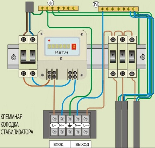
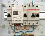
Type of voltage stabilizer terminal block
In houses closer to the substation, the network increases to 240 V, while in remote houses the network remains low. It is also not recommended to use a 240 V network for a long time, since the service life of household appliances is reduced and electricity consumption increases. So you have to install a network voltage stabilizer in the house.
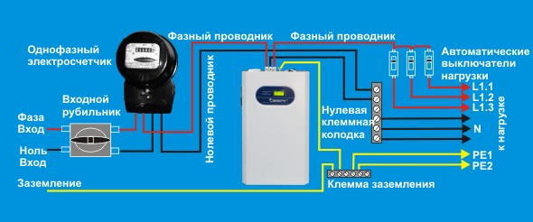
Voltage stabilizer connections diagram for 220 volt network
Before connecting, you must observe safety precautions and turn off the input circuit breaker in the electrical panel before work. After disconnecting the network, check the absence of voltage using a voltage indicator at the input output.
Voltage stabilizer connection diagram alternating current usually indicated by the manufacturer on the back of the device and in the operating instructions.
The voltage stabilizer is connected to the break in the phase wire of the network after the input circuit breaker. The connection diagram can be three-pin - on the stabilizer this is a phase input and a phase output, and a neutral wire.
Connection diagram for a single-phase voltage stabilizer with three terminals
The phase of the input circuit breaker is connected to the input phase terminal of the device, and the output phase terminal of the stabilizer is connected to the phase of the load consumer. The neutral wire, without breaking, is connected to the neutral terminal of the stabilizer.
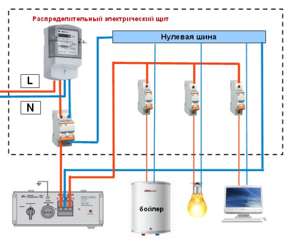
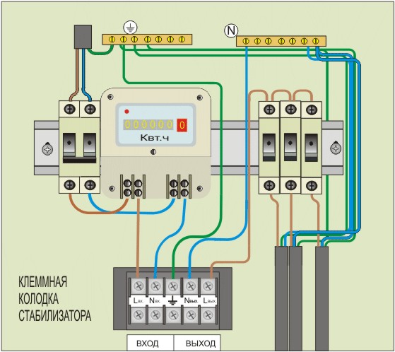
Wiring diagram for connecting a single-phase stabilizer in a panel
If, after the introductory circuit breaker, the network disperses to circuit breakers for lighting and sockets, then the output phase of the stabilizer is connected to them. In the case of only one input circuit breaker, you need to install an insulated block with a terminal in the panel.
The phase wire removed from the input circuit breaker is connected to this terminal. The input phase of the stabilizer is connected to the input circuit breaker, the output of the stabilizer is connected to the installed terminal of the block.
The neutral wire is connected to the stabilizer terminal, and then to the neutral bus of the electrical panel. A variant of stabilizers with two zero terminals is possible, that is, the input phase is zero, the output phase is zero.
Stabilizer connection option with five terminals
Two neutral terminals can be installed for ease of connection and can be interconnected inside the stabilizer. Then the neutral wire is connected as described above.
The zero terminals need to be ringed and if they do not ring, then the second zero terminal is connected to the load neutral wire. First you need to disconnect the neutral load wire in the network from the ground bus in the switchboard.
How to connect a 380V voltage stabilizer
If a three-phase 380V network is installed in the house, then one three-phase alternating voltage stabilizer or three single-phase ones are installed. In the second case, installing single-phase stabilizers will be cheaper. If the load contains a three-phase electric motor, then you need to install one three-phase stabilizer.
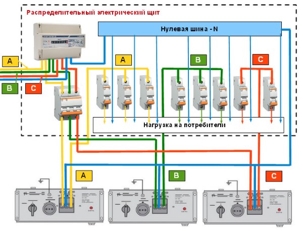
Connecting a three-phase stabilizer in an electrical panel
If the three-phase stabilizer fails, all three phases will be switched off. If one single-phase stabilizer fails, only one phase will fail and the three-phase electric motor will burn out. Before turning on the stabilizer for the first time, turn off all loads except lighting. Turn on the remaining load gradually and at the same time check the operation of the stabilizer. Don't forget to ground the stabilizer housing.
Methods of connecting a voltage stabilizer are determined by its power (purpose). Low-power devices designed to power one electrical appliance, for example, a TV, are not difficult to connect, since they have a power cord with a plug for connecting to the network, as well as an outlet for a standard plug on the cord of a household appliance.
Stabilizers designed to provide supply voltage to all electrical consumers in the apartment, country house or cottages are connected via terminal connectors and require:
- calculating the cross-section of the wires used (determined by the total load power),
- compliance with the order of connecting phase, neutral, grounding.
Options for their connection diagrams, determined by some design features, are given below.
STABILIZER CONNECTION DIAGRAMS
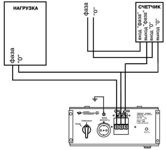
For stabilizers of significant power, the terminal blocks for supplying input and removing output voltages have an appropriate factory markings, therefore, when installing them, it is enough to be careful and accurate. Let's consider the first version of the scheme (Fig. 1).
Here, the terminal for the neutral conductor (N) is combined for the input and output circuits, respectively, two wires are connected to it. Figure 2 shows a stabilizer with two such terminals; accordingly, the “zeros” from the meter and electricity consumers are connected separately. Both of these schemes are extremely simple and are used for a single-phase electrical network with a voltage of 220 Volts.
The next point concerns the three-phase network. If it is used, then it must be used three-phase stabilizer. Its connection is made in the same way as the options discussed above, adjusted for the number of phases.
The use of a circuit with three single-phase devices is possible if there are only 220 Volt consumers distributed over different phases (Fig. 3).

In the previous diagrams, the grounding connection is not shown. The fact is that there is no difficulty here - the corresponding terminal on the device is connected to the grounding conductor (if available). IN otherwise, surrogate improvised grounding conductors such as heating radiators and water pipes are strictly prohibited.
In addition, when connecting several stabilizers, grounding must be connected to each of them with a separate conductor. Series connection of terminals is not permitted.
As an alternative option for ensuring electrical safety, you can use a residual current device.
© 2012-2017 All rights reserved.
All materials presented on this site are for informational purposes only and cannot be used as guidelines or regulatory documents.
The quality of the supplied electricity and certain parameters of the output voltage must meet the requirements of the devices connected to the network. But since it is almost impossible to achieve such indicators without the appropriate equipment, you have to resort to its help. Voltage stabilizers cope best with this task.
However, when selecting such devices, it is necessary to take into account their main characteristics and cost. But even a correctly selected device will not be able to solve the problem without proper installation. Therefore, the search for an answer to the question of how to properly connect a voltage stabilizer should be approached with all responsibility. To begin with, it won’t hurt to familiarize yourself with the structure and operating principle of the equipment.
Design features and scope of application
Devices that make it possible to obtain voltage varying within small limits to power household and other electrical appliances consist of an autotransformer, a switching winding mechanism, and a controller. Moreover, certain components are used for different types of stabilizers.
The following can be used as a switch:
- Servo drive mechanism;
- Relay;
- Keys (thyristors).
However, despite the difference in design, all devices are designed to ensure the normal operation of equipment connected after the stabilizer. Thanks to their use, it is possible to avoid the consequences that arise during various emergency situations in the network, such as:
- Very high or emergency voltage (380V);
- Jumps during switching processes;
- Extreme declines and impulses.
The scope of application of the units is not limited only to household appliances, it is much wider and depends on how the voltage stabilizer works. Such equipment can be used in production to protect various types technology and equipment.
Types of voltage stabilizers
Devices are classified according to several criteria. Depending on the installation method, they can be portable or stationary. The first ones are placed in front of the equipment; they are connected to the network using a standard power plug. They are designed to connect gas boilers, refrigerators, air conditioners, and pumps.
Stationary voltage stabilizers are connected directly to the wiring. You can connect most home appliances through them. They come in single- and three-phase types and may differ in operating principles.

Various types of stabilizers
When creating such equipment, various technical solutions can be used, depending on which stabilizers are classified into the following types:
- Relay;
- Triac;
- Electromechanical;
- Ferroresonant.
Each model has its own characteristics. Therefore, when choosing a specific type of equipment, its main parameters are taken into account.
Relay stabilizers consist of an autotransformer and a power relay controlled by an electronic circuit. Switching of windings in such a device is carried out automatically, and the principle of operation is based on step adjustment.
Equipment of this type is not particularly accurate in its output parameters and is therefore recommended for use with low-power household appliances.
Triac or electronic stabilizers are capable of operating almost silently, since they do not have a mechanical relay. But since the adjustment is carried out using a relay type, it is impossible to obtain high accuracy. At the same time, if we compare them with relay devices, they cost 3 times more, so they are not widely used.
Servo drive units are equipped with an electric drive responsible for moving the contacts along the winding of the autotransformer. They have smooth adjustment, but cannot be used with networks where there are rapid voltage surges.
Ferroresonant stabilizers are designed to regulate voltage within a given range. Their operating principle is based on the ferroresonance effect. However, this type of equipment has limitations in its use due to certain technical issues.
Preparing for work
Selection and purchase is only the initial stage that you will have to face if you decide to protect your household appliances from emergency situations in the electrical network. The next step should be to find an answer to the question - how to connect and install a voltage stabilizer?
connect the stabilizer to your home network
So, before starting installation work, you need to remove the device from the packaging and inspect it for possible mechanical damage. If the stabilizer has been at a negative temperature for a long time (during transportation), it should be kept for at least 2 hours before connecting it to the network. This will avoid the appearance of condensation when the equipment heats up during operation.
Next we move on to the question of how to install a voltage stabilizer for the home? The equipment may be installed indoors, where it will not be exposed to construction dust or other aggressive environments. There should be no flammable materials near the stabilizer.
Watch the video, connection steps:
The device body must be grounded, and the connection to the network is made through the corresponding pair of terminals located on the rear panel. The stabilizer is turned on using a circuit breaker; the voltmeter should show 220 V. A load is connected to the output terminals and only after that can the switch be turned on.
How to calculate stabilizer power
To choose the right model, you need to decide which electrical appliances will be connected to the device. You can determine their power consumption using one of the methods provided on the Internet or use the simplest of them. It is as follows. There is a circuit breaker on the electrical panel, the rating of which is selected in such a way as to protect the wiring from damage due to overload.
Watch the video to correctly calculate the power of the device:
But how to calculate the power of a voltage stabilizer for your home? From the physics course we know that this parameter is equal to the product of current and voltage. The values of these quantities are easy to determine. The voltage in a single-phase network is 220V, and the rated current is usually indicated on the circuit breaker. Let's say it is 16A, then the power will be 16*220=3520 W. But you need to choose a stabilizer with a margin of at least 30%. This is due to the fact that as the voltage increases, the output power drops.
In addition, you need to focus not on the full, but on the active power of the device - this is important to know!
Device malfunctions and their solutions
Possible options for equipment failure are usually given in the documentation supplied with it. Among them, the following malfunctions most often occur:
- Spontaneous shutdown of the device usually occurs due to exceeding the permissible load;
- The network indicator light does not light up if the device is not connected, the fuse is faulty or the connections are mixed up;
- It is not possible to achieve an output voltage of 220 V with an unacceptable load;
- There is no stabilization - this may be due to problems with the input-output button or turning off the Bypass mode.
Many consumers are interested in the answer to this question. Those who believe that this can increase the power of the stabilizer are mistaken. On the contrary, the output parameters will correspond to the value produced by the weakest device in the network. For example, if three devices of 5;10;15 kW were connected in parallel, then the output power will be only 5 kW, since this figure is the lowest.
Many owners of country private houses sometimes have to face a very unpleasant situation. The light of the lamps dims, refrigerators begin to “cough” and stop, microwaves and conventional electric ovens hardly heat up.
This occurs when the voltage in the electrical network supplying the house drops.
As a rule, this phenomenon is seasonal.
In holiday villages - from late spring to early autumn, with a sharp “exacerbation” on weekends.
In villages this is a cold period, from November to May.
The reason for this is very simple - there is not enough power at the local transformer substation.
With the massive arrival of summer residents, electricity consumption increases, transformers simply cannot produce more power than the nominal value - the output voltage drops.
The same thing can happen with the massive use of electric heating devices for heating rooms in the cold season.
There are two real ways out of this situation.
The first organizational solution is to collect money from everyone possible and try to find a specialized installation organization that has the ability to modernize an existing substation or install a new one.
The second output is individual - you can install a modern automatic voltage stabilizer in your home. There are now similar devices on sale that are capable of raising the “dropped” mains voltage from 90V(!) to normal 220 volts.
The range of adjustable voltage is a value that must be specified in the technical data sheet of the stabilizer. In addition, voltage stabilizers can have different powers. Guided by these two parameters, people usually choose a stabilizer based on the existing need.
If the main problem is a refrigerator that refuses to work and is about to burn out, you can buy a very inexpensive low-power stabilizer. A 0.6 - 1.5 kilowatt device is more than enough - after all, the power consumption of household refrigerators rarely exceeds 250 watts.
In addition, stabilizers designed for low power, as a rule, do not require special connections. Equipped with el. plug and cord, they can easily be plugged into any nearby electrical outlet. socket. The payload (refrigerator) is connected to an electrical outlet located on the front panel of the device.
If it is necessary to increase the voltage throughout the house, a more powerful stabilizer is needed. How to choose its power? It is necessary to take into account the power of all electrical appliances that you plan to use regularly.
You need to add them together and multiply the resulting value by 1.3. This will be the optimal power value for a common house voltage stabilizer. Such stabilizers require a special connection - a procedure that is not particularly difficult.
The stabilizer is connected to the network after the meter at the input of the electrical wiring of the room, in series with the break in the supply wire. The terminal block for connecting the supply wires is most often located on the back side of the case (less often on the front side).
Two wires coming from the meter are connected to the input, the phase wire to terminal L, the neutral wire to terminal N. The common zero bus of the distribution board is connected to terminal N of the output, and the circuit breakers are connected to terminal L.
All stabilizers, as a rule, have a built-in circuit breaker for protection against short circuits and overloads. For additional protection of the electrical circuit and the possibility of manual shutdown (for repairs), an additional “automatic circuit breaker” of the required rating must also be installed in front of the stabilizer (before or after the meter).
A modern house, both private and multi-apartment, consumes a significant amount of electricity. If you sum up the electrical power of all devices that are turned on in a modern apartment in the evening, from phone and computer chargers to a washing machine and iron, you will get a fairly significant figure. Naturally, the communal energy system, which was designed based on a much smaller load, cannot cope and begins to fail. Therefore, the result is voltage surges in the network.
Types of stabilizers and their choice
To protect your home network from voltage surges and ensure stable operation of complex electronic devices both at low and high voltage values, a stabilizer is usually connected. There are three types of household voltage stabilizers - electromechanical, electric relay and electronic. The electromechanical one consists of a motor and an autotransformer, the electrical relay one consists of an autotransformer and a relay system, and the electronic one is made on the basis of high-voltage semiconductor devices - triacs.
The electromechanical stabilizer is the cheapest. However, it is designed to operate only in the positive temperature range, and has some lag under large and frequent voltage surges. In addition, it makes little noise during operation; it must be cleaned and lubricated once a year, and should only be installed on a strictly horizontal surface. An electric relay is a little more expensive and can be installed on a wall, but it will also require changing the relay from time to time, especially with frequent voltage surges. Relay switching produces a characteristic click, which is clearly audible and not always pleasant. The most expensive is electronic, based on triacs. Such a device has smooth adjustment, even with the most frequent and large voltage surges in the network, good protection, and practically does not require maintenance.
Network connection
It is best to entrust the connection of the stabilizer to professionals. It would also be nice if a specialist electrician took part in choosing a stabilizer. If this is not possible, and you have to do everything yourself, you can give some simple tips.
Before choosing a stabilizer, be sure to estimate the maximum power consumption of all electrical appliances that it will have to “serve.” The stabilizer power should exceed it by 25-30%, or even more, in case you plan to increase it in the future.
The stabilizer is connected after the electric brush. A plug or automatic switch must be placed in front of the stabilizer, which is designed for the maximum current in the stabilizer. Then the stabilizer itself turns on. Before, how to properly connect a voltage stabilizer to the network, you should read the instructions carefully. The stabilizer may have a built-in bypass circuit, or you can create one yourself. Bypass is a spare connection method that allows you to supply voltage directly, bypassing the stabilizer. After the stabilizer, machines are installed on the household network. Typically, a 6A automatic circuit breaker is installed for lighting, an 8A circuit breaker is installed on the electrical network to which a computer, TV, and other electronic devices are connected, and an 8A circuit breaker is installed on the electrical network from which washing machine, iron, electric cooker - 12A or even higher. It is advisable to separate the outlets to which these electrical appliances are connected.